
Safety & Compliance
Follow safety and compliance guidelines for operating the ALPON X4 edge computer. Ensure proper handling and industrial certification standards.
Operate the ALPON X4 safely and within spec
Handling, power, thermal, antenna, port, and regulatory rules for the ALPON X4 industrial edge IoT computer. Review every section before powering, mounting, or deploying the device in the field. Built on Raspberry Pi.
The ALPON X4 is a fanless industrial edge IoT computer
rated for −20 to +60 °C ambient and IP40,
powered by one of three inputs: 9 to 30 V DC on the
terminal block, USB-C PD at 15 V (27 W minimum),
or PoE+ on the ETH/G port (PoE-variant SKUs only).
Regulatory certifications (CE, FCC, IC, UKCA, GCF, PTCRB, RCM, ICASA,
RoHS, WEEE, REACH) are currently in progress and will
be confirmed in this document once issued. Use only one power input at a time.
Never connect Ethernet or PoE to the GPIO Add-on port; doing
so causes permanent hardware damage. Built on Raspberry Pi.
The GPIO Add-on port uses an RJ45 socket but exposes 3.3 V GPIO, SPI, UART, and I²C signals, plus a 5 V at 1 A output rail for attached modules. Connecting an Ethernet cable or a PoE source will cause permanent hardware damage. Use the port only with Sixfab GPIO add-on modules.
Safety reference at a glance
Key environmental and electrical limits for safe operation. The full envelope and unit conventions follow Cornerstone §15 and the ALPON X4 specifications page.
ETH/G onlyGeneral handling
Universal rules that apply to every installation, regardless of power source or mounting orientation.
The aluminum enclosure acts as a heatsink and may reach high temperatures during sustained workloads. Avoid touching the top cooling surface during extended operation or immediately after shutdown.
The device is rated IP40. Keep it away from liquids, condensation, and flammable materials. Direct outdoor exposure requires a separate protective enclosure.
Apply standard ESD precautions (wrist strap, grounded mat) when handling the device with the enclosure open or working near exposed connector pins.
The ALPON X4 contains no user-serviceable parts. Opening the enclosure voids the warranty. Contact Sixfab support for any internal repair or modification.
Do not insert metal or conductive objects into ports, vents, or connectors. Avoid impact damage to the aluminum housing and SMA antenna connectors.
Power safety
Three independent inputs (DC terminal block, USB-C PD, PoE+ on PoE-variant SKUs). Use only one input at a time to keep voltage precedence defined.
How do I power the ALPON X4 safely?
ETH/G only. PoE-variant SKUs only.
Power source selection
Use only one power input at a time. Connecting two or more inputs simultaneously is not recommended and can lead to undefined voltage precedence between sources.
Typical consumption is 7 to 14 W with a 27 W peak under full load. Match the adapter rating to the workload, including current drawn by connected USB peripherals.
PoE+ is available only on variants that include the built-in PoE module. The module cannot be added in the field. Use a PoE+ (IEEE 802.3at) Class 4 injector or switch supplying 37 to 57 V; legacy PoE (802.3af) cannot deliver enough power for the ALPON X4.
Power is sourced only through ETH/G. Do not connect PoE to the ETH port. The 100 Mbps ETH port does not deliver power to the system.
Never supply voltage below 9 V or above 30 V through the terminal block. Operating outside the rated range can damage internal regulators and is not covered by the warranty.
DC terminal block wiring
The DC terminal block uses a 3-pin layout with marked polarity. Wire it exactly as shown to avoid tripping the reverse-polarity protection.
For DC power over long cable runs, prefer a 24 V adapter with a sufficiently thick conductor to compensate for voltage drop. A 12 V source at the far end of a long cable can drop the input close to the lower limit.
USB-C PD requirements
Use a USB-C PD adapter that delivers 15 V at ≥1.8 A (27 W). Use the adapter included in the package for guaranteed compatibility.
Standard 5 V USB-C chargers and PC USB ports are not supported for normal operation. The USB-C port requires a USB-PD-capable source negotiating 15 V.
The USB-C port is sink-only. It cannot be used as a USB host, USB peripheral interface, or power output.
Non-compliant USB-C cables can drop voltage under sustained load even with a capable adapter. If consumption approaches 27 W, swap cables for ones rated above the minimum.
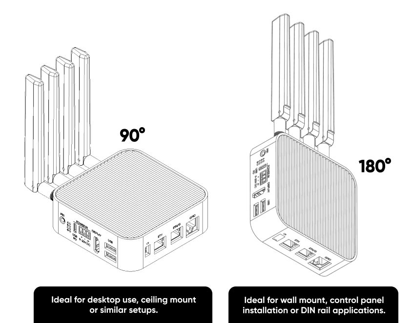
Thermal safety & mounting
The fanless aluminum top is the primary heatsink for the Raspberry Pi CM4. Mounting orientation directly affects sustained throughput.
Recommended mounting orientations
Environmental clearances
Keep the device away from direct heat sources (ovens, motors, boilers) and steam. Radiant heat reduces ambient headroom against the +60 °C operating limit.
When enclosing the ALPON X4 in a cabinet, provide at least 25 mm of clearance around the cooling surface and verify cabinet ventilation is adequate for the combined heat load.
Two 4 mm mounting holes on the rear of the enclosure support DIN rail or wall mounting with the appropriate accessories. Ensure mounting hardware does not contact the cooling surface.
Antenna & RF safety
Four SMA ports for LTE Main, LTE Diversity, Wi-Fi/Bluetooth, and GNSS/GPS. Connector genders differ by port — match the antenna gender to the port when ordering replacements.
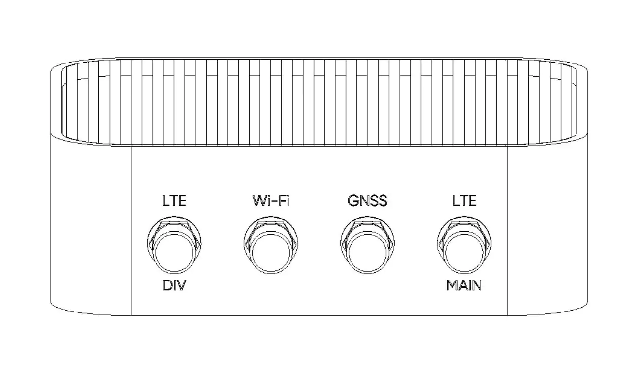
Antenna specification
The Wi-Fi port uses a male SMA connector, while the GNSS and LTE ports use female SMA connectors. Match the antenna gender to the port before ordering to avoid adapter chains and impedance mismatches.
Installation & handling
Never install, remove, or service antennas while the device is powered on. Disconnect every power source first to prevent electric shock and RF transmitter damage.
Hand-tighten SMA connectors firmly without over-torquing. For field installations use a 6 mm SMA torque wrench at 0.5 to 0.7 N·m.
Inspect connectors for corrosion, debris, or damage before each reattachment. Replace compromised connectors rather than forcing a fit.
For outdoor or harsh environments, use the optional 3-meter cabled IP67 combination antenna with surface mount instead of the bundled stub antennas.
Placement & signal quality
Do not swap antennas between ports. LTE, Wi-Fi, and GNSS ports are tuned for different frequency bands; mismatched antennas degrade link quality and may overload the RF front-end.
Keep antennas clear of metal surfaces, reinforced concrete, and other sources of electromagnetic interference such as microwave ovens, cordless phones, and large motors.
The GNSS antenna must be placed in an open area with the top facing the sky. Obstructed or ground-level placement degrades time-to-first-fix and position accuracy.
Port & connector safety
Several ALPON X4 ports share physical form factors with unrelated standards. Read the port-specific rules before cabling.
GPIO Add-on port: not an Ethernet port
The GPIO Add-on port uses an RJ45 jack but exposes 3.3 V GPIO, SPI, UART, and I²C signals, plus a 5 V at 1 A output rail for attached modules. It is not wired for Ethernet or PoE.
Connecting an Ethernet cable or a PoE source to the GPIO Add-on port can permanently damage the device. The GPIO lines run at 3.3 V logic; PoE voltage (up to 57 V) destroys the signal pins and the level shifter. Use the GPIO Add-on port only with Sixfab GPIO add-on modules.
Port function reference
USB 2.0 port output limit
The two USB 2.0 host ports share a combined 5 V at 1 A total output budget. Plan accordingly when attaching peripherals.
When attaching high-draw USB peripherals (SSDs, cellular dongles, external hubs), budget current across both ports together, not per port.
For USB peripherals that exceed the on-device budget, use a powered USB hub with its own external supply.
Watchdog & Boot/Burn DIP switches
Two DIP switches control firmware-level behavior: Watchdog enable/disable and Boot/Burn mode.
Watchdog DIP. When enabled, the host must strobe the watchdog GPIO within the configured window or the device hard-resets. Disable only for development or controlled shutdown scenarios.
Boot/Burn DIP. Set to Burn only for image flashing via Raspberry Pi Imager over USB-C. Return to Boot before resuming normal operation, and power-cycle the device after toggling.
Fully disconnect every power source before changing the Boot/Burn DIP position. Toggling under power leaves the bootloader in an undefined state.
Regulatory compliance & certifications
Regulatory certifications for the ALPON X4 are currently in progress. The device is being tested and submitted for the certification marks required to ship in the European Union, the United States, Canada, the United Kingdom, Australia/New Zealand, South Africa, and for international cellular acceptance. This page will be updated as each certification is issued.
The certifications listed below are the targeted regulatory marks for the ALPON X4. Test campaigns are under way at accredited labs but no certificate of conformity has been issued yet. Do not rely on these as final compliance evidence; for procurement, RFP, or pre-production deployment decisions, request the current status letter from Sixfab and wait for the official Declaration of Conformity (DoC) once available.
Targeted certifications
Test standards under evaluation
The ALPON X4 is being evaluated against the following standards as part of the in-progress certification campaign. Listing a standard here means testing is planned or under way, not that a pass result has been published.
Need the current certification status, target completion dates, or interim test evidence for procurement decisions? Reference the device model and serial number from the label on the enclosure when contacting Sixfab.
Request status updateFCC Class B notice (target)
Once FCC certification is issued, this equipment is expected to comply with the limits for a Class B digital device, pursuant to Part 15 of the FCC Rules. These limits are designed to provide reasonable protection against harmful interference in a residential installation. Final certification will subject operation to the following two conditions:
- This device may not cause harmful interference.
- This device must accept any interference received, including interference that may cause undesired operation.
Once certifications are issued, changes or modifications not expressly approved by Sixfab can void the user's authority to operate the equipment under FCC and IC rules. Treat unmodified, factory-supplied hardware as the only configuration covered by the future Declaration of Conformity.
Environmental & end-of-life
Designed to meet RoHS, WEEE, and REACH directives. Follow these rules at end-of-life.
Do not dispose of the device in unsorted household waste. Return it through an authorized WEEE collection point, a local electronics recycler, or back to Sixfab for responsible processing.
The ALPON X4 contains a CR1220 coin-cell battery for the real-time clock. The battery is accessible only through authorized service and must be disposed of separately at end-of-life.
Before disposal or return, erase sensitive data from the eMMC and any connected storage. Retain the original packaging for return shipping.
Warranty
The ALPON X4 ships with a 2-year limited warranty against manufacturing defects. The warranty does not cover damage caused by:
- Power input outside the rated envelope (below 9 V, above 30 V, or non-compliant PoE injectors).
- Connecting Ethernet or PoE cables to the GPIO Add-on port.
- Unauthorized modification of firmware, enclosure, or internal modules.
- Operation outside the rated environmental envelope (−20 to +60 °C, 95% non-condensing humidity, IP40).
- Physical damage from impact, liquid ingress, or electrostatic discharge.
- Failure to follow the safety and usage instructions in this document.
Submit warranty claims with the device serial number, purchase date, and a description of the fault.
Contact SixfabUpdated about 2 months ago