
Physical Layout & I/O
Explore the hardware layout and I/O interfaces of the ALPON X4 edge computer. Understand ports, connectivity, and expansion options.
ALPON X4 physical layout & I/O
Pinouts, ports, indicators, and electrical characteristics for every externally accessible interface on the ALPON X4 industrial edge computer. Use this reference to wire the device, drive its GPIO from software, and plan field installations. Built on Raspberry Pi.
The ALPON X4 exposes 3 power inputs (USB-C PD, 9–30 V DC terminal, optional PoE+), 1× Gigabit Ethernet and 1× 100 Mbps Ethernet, 2× USB 2.0 (1 A shared), HDMI 2.0 for display up to 4Kp30, an RJ45 GPIO Add-on port (I²C / UART / SPI at 3.3 V logic), 4 LED indicators, 2 user buttons, and 2 DIP switches for watchdog and image-flash mode.
Device layout
The ALPON X4 is housed in a fanless aluminum enclosure. All I/O is split between the front face (power, USB, display, indicators) and the rear face (Ethernet, GPIO, antennas, switches). Click any image to enlarge.
Front face
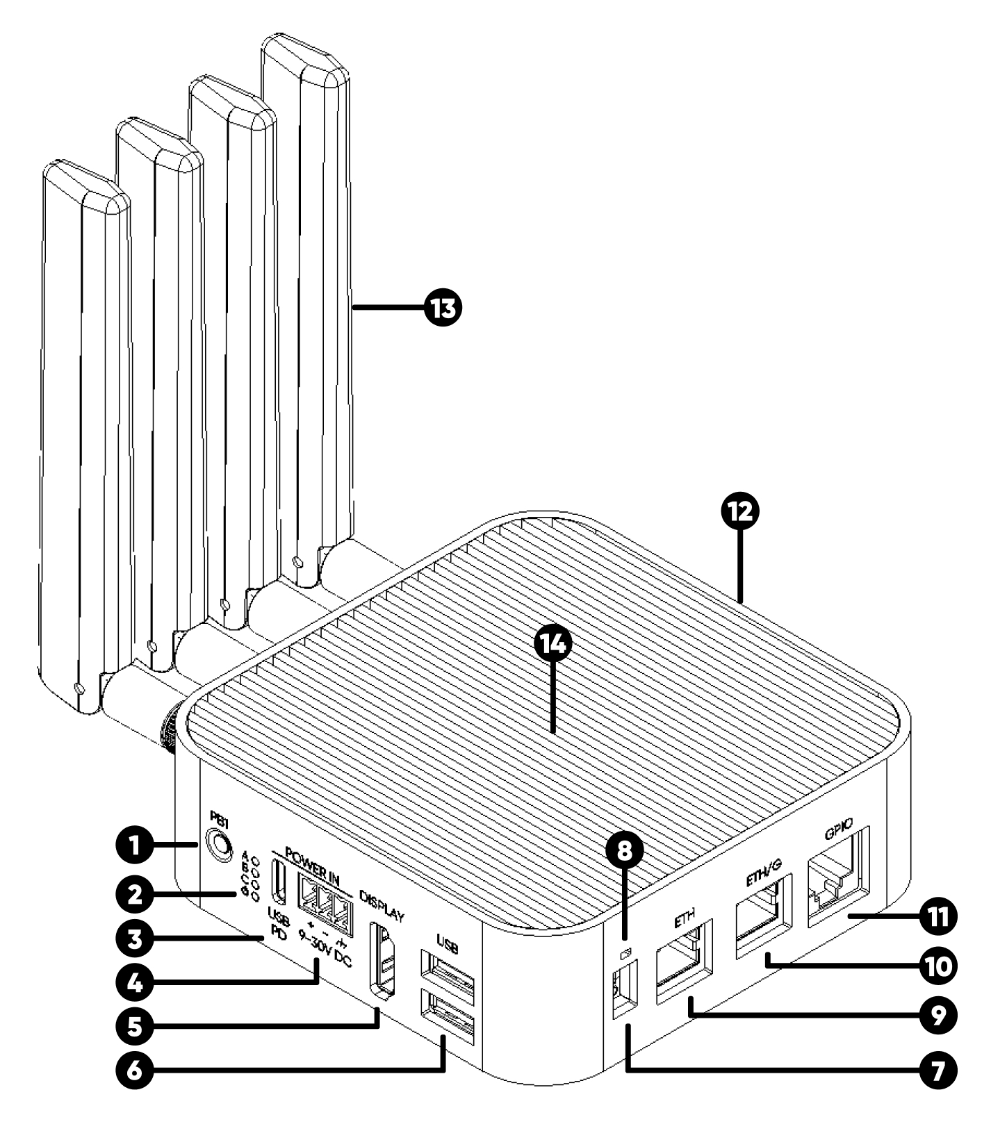
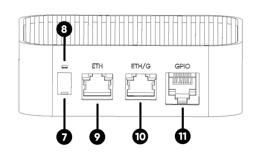
Rear face
Enclosure
Mechanical specifications
Need mounting templates or dimension drawings?
Mounting templates, hole patterns, and dimension files are on the Power & Mounting page.
Power input
The ALPON X4 accepts power from three independent sources. There is no hard priority between inputs: the device draws from the source with the highest voltage. All inputs pass through ideal-diode protection.
The device must be operated with only one power input at a time. Connecting two or more power sources simultaneously is not recommended in production deployments — use a single source to simplify failure analysis and avoid ground loops.
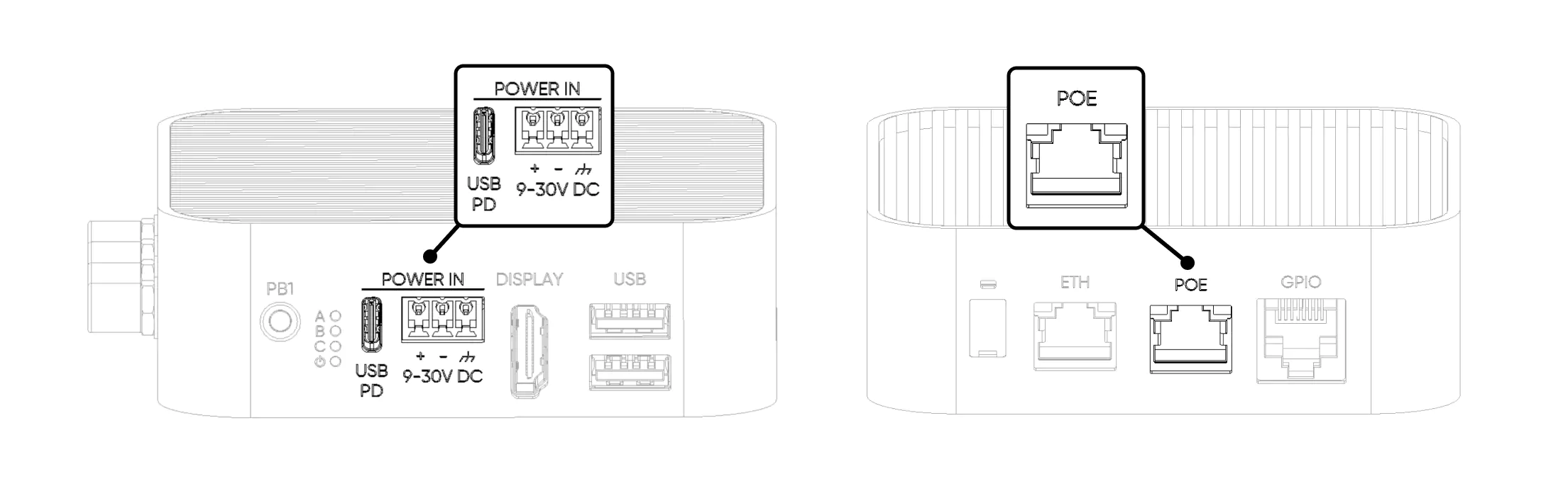
USB Type-C PD
Sink-only USB-PD port. Does not provide USB data or output power during normal operation. USB data is available only when SW2 is set to Burn (image flashing) mode.
CYPD3177-24LQXQ
Powering the device at 5–12 V via USB-C forces the system into Restricted Mode to prevent brownout.
Screw terminal (9–30 V DC)
The recommended input for industrial edge computing deployments. The 3-pin terminal includes hardware reverse-polarity protection: swapped wiring will not damage the device, but it will not power on either.
Power over Ethernet (PoE+)
PoE+ is available only on PoE-variant SKUs. The PoE+ module is built into the device and cannot be added separately. When present, PoE+ is wired to the ETH/G port; the 100 Mbps ETH port does not accept PoE.
Restricted Mode
When USB-C is supplied at the 5–12 V range (below the 15 V PD profile), the device cannot guarantee enough headroom for every subsystem and enters Restricted Mode. Core compute and network paths stay online; high-draw peripheral rails are cut to prevent brownout.
Core subsystems keep running so the device stays reachable.
- CM4 Compute Module
- LTE Modem
- ETH (100 Mbps)
- ETH/G (1 Gbps)
High-draw interfaces are disabled to prevent brownout.
- USB 2.0 Ports
- GPIO Add-on 5 V Rail
- HDMI Display
- Programmable RGB LED
Power consumption
Approximate consumption profile at 12 V DC input. Values depend on workload, attached peripherals, and active radios. A 27 W supply covers every supported configuration.
Ethernet ports
Two RJ45 Ethernet ports with different link speeds and electrical topologies. Use both for WAN + LAN routing, dual-NIC redundancy, or isolating trusted and field segments.
ETH/G 1 Gbps PoE+
Gigabit Ethernet via USB-to-Gigabit bridge. Carries PoE+ on PoE-variant SKUs.
ETH 100 Mbps
Native CM4 Ethernet port. 100 Mbps Fast Ethernet, no PoE.
On some PoE variants, the ETH/G port is replaced by the PoE+ input. Check your specific SKU before planning network topology.
USB 2.0 ports
Two USB 2.0 high-speed ports. Devices connected here are recognized as directly attached to the Raspberry Pi CM4 USB controller. Both ports share a combined 1 A power budget.
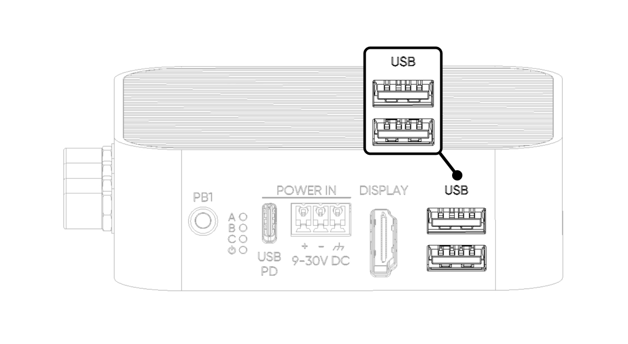
You can connect a single device drawing up to 1 A, or two devices with a combined draw of no more than 1 A. If this limit is exceeded, power to both ports cuts off and a full device reboot is required to restore.
Display (HDMI 2.0)
Single HDMI 2.0 port driven directly by the CM4. Connects to a standard monitor with an HDMI cable. Supports up to 4K @ 30 Hz.
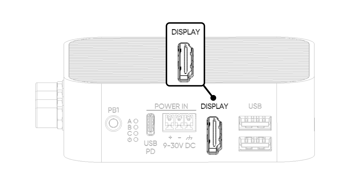
Display detection runs at boot. For first-time setup or headless-to-monitor transitions, plug in HDMI before powering the device.
GPIO Add-on port (RJ45)
The GPIO Add-on port exposes six configurable CM4 pins over an RJ45 connector, providing I²C, UART, and SPI for ALPON Edge Add-on modules. Signals are 3.3 V logic routed through an on-board level converter for stability on long cable runs.
Although the connector is RJ45, this port is not Ethernet and not PoE-capable. Connecting it to a switch, router, or PoE injector will cause permanent hardware damage. Use only with compatible ALPON Add-on modules.
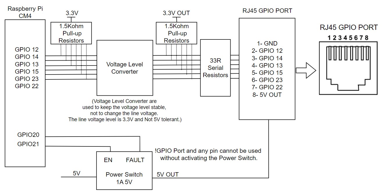
Pin assignment
GND · Ground
GPIO 12 · SPI5_CSn[0], UART4_TX, I2C2_SDA
GPIO 14 · SPI5_SIO[0], UART0_TX, I2C3_SDA
GPIO 13 · SPI5_SIO[1], UART4_RX, I2C2_SCL
GPIO 15 · SPI5_SCLK, UART0_RX, I2C3_SCL
GPIO 23 · I2C3_SCL
GPIO 22 · I2C3_SDA
5V OUT · 5 V output, max 1 A. Gated by GPIO 21 power switch
Electrical characteristics
GPIO 21 · must be HIGH before I/O
GPIO 20 · HIGH normally, LOW on fault
The voltage level of all pins is 3.3 V. Pins are not 5 V tolerant. Driving them above 3.3 V can damage the CM4.
Enabling the port from software
The 5 V supply and signal I/O are gated by an on-board power switch. Drive GPIO 21 HIGH to activate the port, then read GPIO 20 to confirm no fault is asserted.
ADDON_PWS_EN
GPIO 21 · Drive HIGH to activate the port. I/O is inactive while LOW.
ADDON_PWS_FAULT
GPIO 20 · Reads HIGH normally. Goes LOW on overcurrent or short-circuit events. Returns HIGH once the fault clears.
# 1. Enable the GPIO Add-on port power rail
pinctrl set 21 op dh      # drive GPIO 21 HIGH
pinctrl get 20            # read fault line, expect 1 (HIGH)
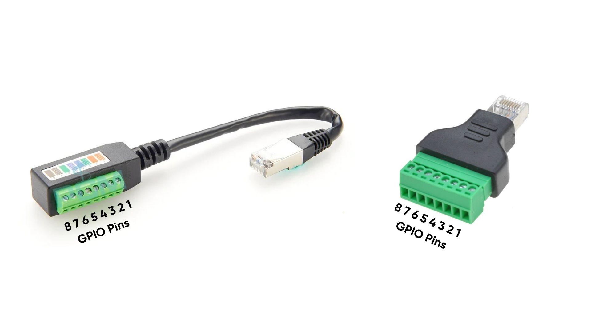
RJ45-to-terminal block adapter
When optional RJ45-to-terminal block adapters are attached, the GPIO port pins are mapped to screw-terminal positions for easy field wiring.
LED indicators
Four LEDs on the front face report system state. All LEDs are driven through the TCA6408A I²C I/O expander at address 0x20 on the I²C1 bus (SDA: GPIO 2, SCL: GPIO 3).
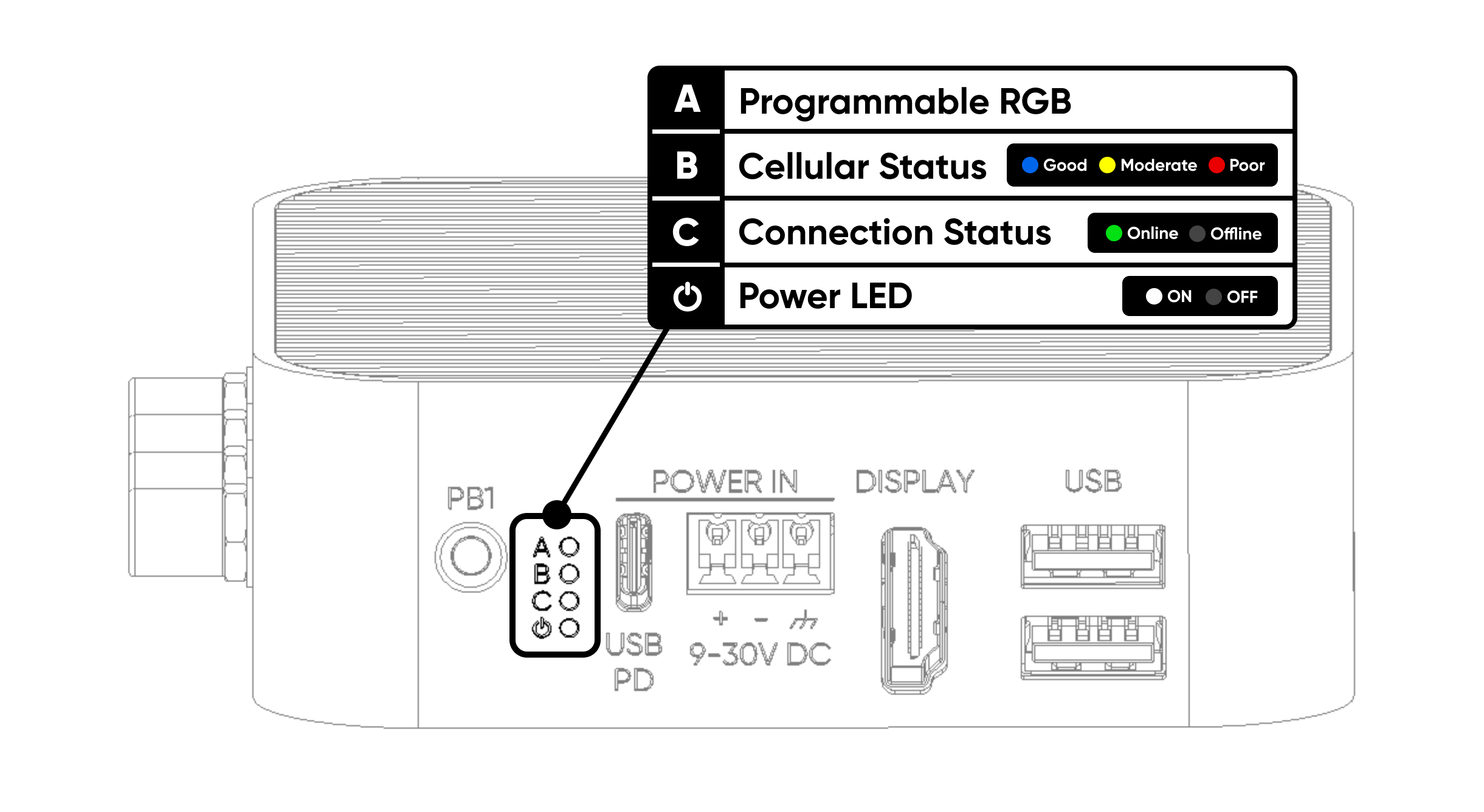
Freely programmable. Set color by writing the corresponding R/G/B expander pins to LOW.
Red: poor signal · Yellow: moderate · Blue: good connection.
Lights green when the device is reachable via Sixfab Connect.
Turns white about 3 seconds after the device powers on.
The Programmable RGB LED is wired to expander pins P2 (Red), P3 (Green), and P4 (Blue). Set the corresponding pin LOW to turn that color on. A reference Python script that cycles through red, green, and blue is available as a GitHub Gist.
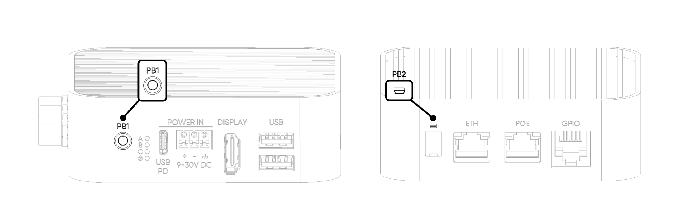
Push buttons
Two user-programmable buttons: PB1 on the front face and PB2 on the rear. Both lines are pulled HIGH by default and read LOW while pressed. Both can be assigned to different functions in software.
GPIO 5 · Pulled HIGH · LOW when pressed · user-defined action
GPIO 6 · Pulled HIGH · LOW when pressed · user-defined action
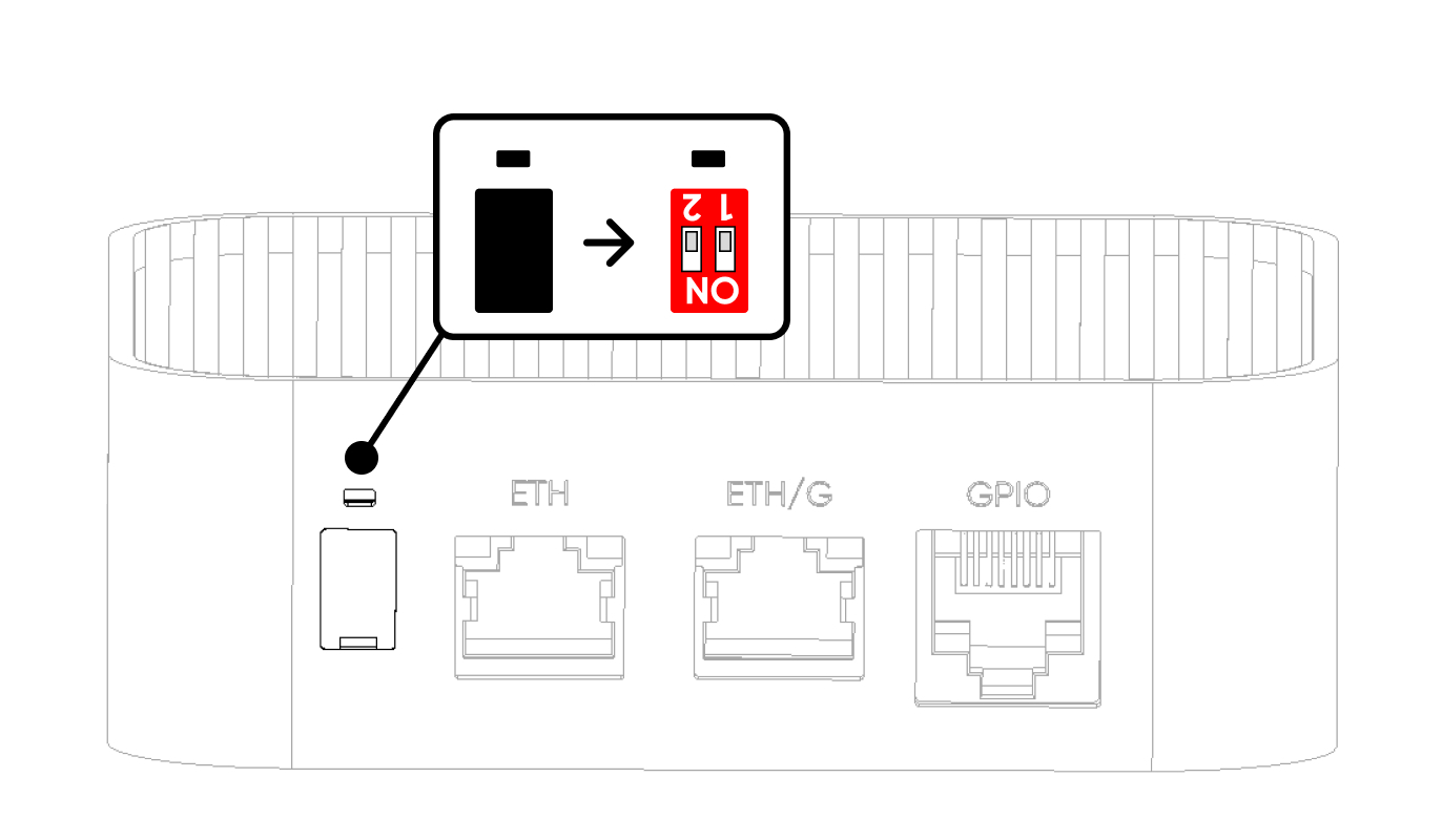
Watchdog & Boot/Burn switches
Two DIP switches sit under a silicone cap on the rear face. Both ship OFF by default and should remain OFF during normal operation. Use a pointed tool to lift the cap from its notch.
SW1 · Hardware watchdog
The hardware watchdog monitors device operation independently of the OS. When active (SW1 OFF), the device resets in case of failure. The watchdog runs on dedicated logic and cannot be disabled in software — only by physically toggling SW1.
SW2 · Boot / Burn mode
SW2 selects between normal operation (Boot) and CM4 image flashing over USB-C (Burn). In Burn mode, the USB-C port exposes the CM4 flashing interface to a host PC.
The device must be completely powered off when switching between Boot and Burn modes. Both switches are set to OFF by default from the factory and no changes are needed during normal operation. If either switch has been changed, set both back to OFF before powering the device. Toggling switches in modes other than Boot and Burn can prevent the device from achieving maximum uptime.
If an image is damaged or needs reflashing, contact Sixfab support before attempting the flash. Trying to reflash the image without guidance may cause more issues.
Antenna connectors
Four SMA connectors on the enclosure carry the wireless interfaces. Labels on the enclosure identify each port.
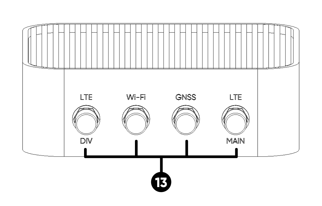
The Wi-Fi port uses a male (RP-SMA) connector; GNSS and both LTE ports use female connectors. Supplied antennas are keyed accordingly. Verify thread compatibility before forcing a connection.
Radiation patterns & certified bands
LTE band list, antenna gain, and certified RF specs.
Internal bus topology
How each external interface maps back to the CM4. Useful for diagnosing throughput limits and shared-rail behavior.
TCA6408A @ 0x20 · Expander-driven
GPIO 21 power switch
GPIO 5 (PB1), GPIO 6 (PB2) · Pulled HIGH, LOW when pressed
Updated 13 days ago