
Technical Details
This section introduces the concepts and terms that are crucial for the understanding, implementation and use of Base HAT.
Product name and Model name: 3G/4G & LTE Base HAT - S121
Rated input voltage(V): 5V DC
Rated input current(A): 3.0A
Max. operating and storage temperature: -25°C to 70°C
Product specification: Cellular Modem - Smart Card Carrier Board
Use method of product: Data transmission over mobile broadband
Precautions or Warning
The Sixfab Base HAT contains highly sensitive electronic circuitry and is an Electrostatic Sensitive Device (ESD). Handling the board or modems without proper ESD protection may destroy or damage it permanently. Proper ESD handling and packaging procedures must be applied throughout the processing, handling and operation of any application that incorporates the board. ESD precautions should be implemented on the single-board computer where the Base HAT is stacked. Failure to observe these precautions can result in severe damage to the module!
Pinout

Pin Descriptions
| Pin Number | BCM Pin | Pin Name | Description |
|---|---|---|---|
| 8 | UART_TX | PCI RX | This pin functions as the serial data input to the module for UART communication. Disconnected by default. |
| 10 | UART_RX | PCI TX | This pin functions as the serial data output from the module for UART communication. Disconnected by default. |
| 13 | GPIO27 | USER LED | Active HIGH, to switch on the USER LED, the pin's state should be HIGH. |
| 15 | GPIO22 | USER BUTTON | This pin normally pulled-down to ground. When the button is pressed, pin switches to HIGH. |
| 31 | GPIO6 | RI | This pin is Ring indicator functions as the indication for receiving call or SMS, can be calibrated to HIGH or LOW using the AT commands. |
| 33 | GPIO13 | DTR | When the module is in sleep mode, DTR pin allows to wake the module up by pulling it to LOW. |
| 35 | GPIO19 | W_DISABLE | This pin is used to turn Airplane Mode on the module, by pulling it HIGH. |
| 37 | GPIO26 | HAT_PWR_OFF | Power regulator control. Normally pulled-down, when this pin drove to HIGH, Hat's power will cut off. |
Layout

Compatible Mini PCIe Modules
| Manufacturer | Module |
|---|---|
| Quectel | EC25, LTE-EP06, EC21 , EC20 Mini PCIe LTE IoT Module, UC20 , LTE-EP06 |
| Telit | LM960, LE910V2, HE910,LE910C1, LE910C4, and more |
| Thales | PLS62W, mPLS8, mPLAS9 |
| Sierra | AirPrime MC Series |
| Huawei | ME909s-120, ME909s-821, and more |
| Simcom | SIM7100, SIM7230, and more |
| ZTE | ZM8620, and more |
| U-Blox | MPCI-L2 Series |
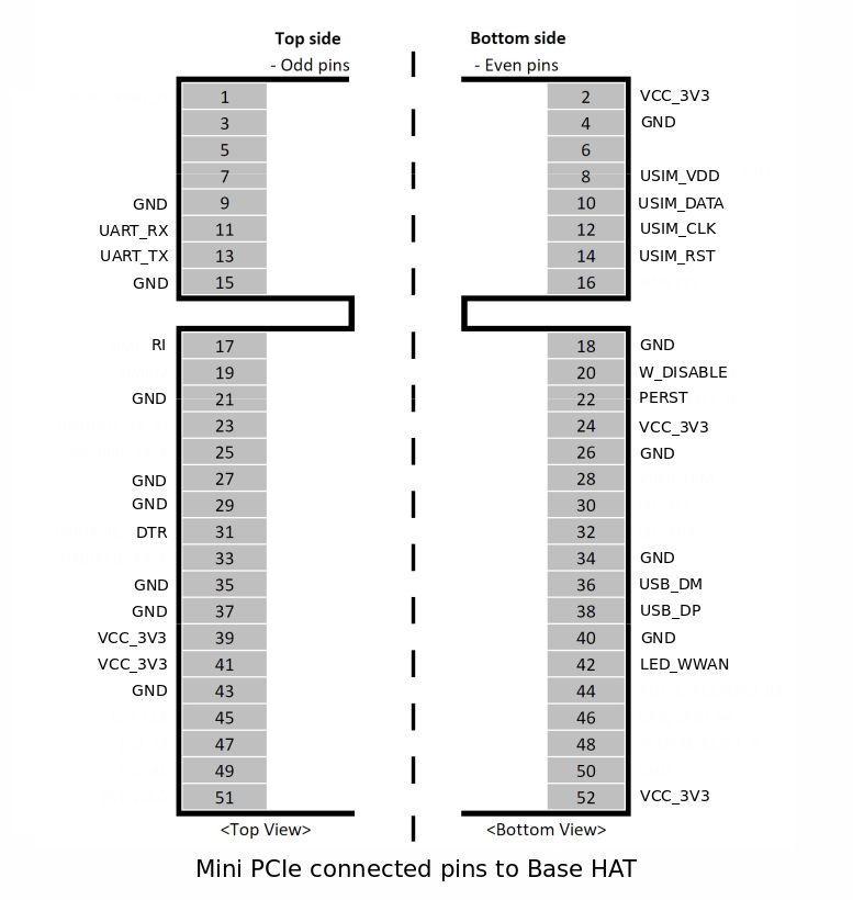
Use of different mini PCIe modules with Base HAT
If one is looking to use different mini PCIe modules other than the ones mentioned above, it should be compared with the pinout of mini PCIe below. The following mentioned pins are connected to the Base HAT. The minimum requirement is to match VCC_3V3, GND, USIM_VDD, USIM_DATA, USIM_CLK, USIM_RST, USB_DM & USB_DP
Compatible Boards
- Raspberry Pi 4, 3, 2, B+, A+, Zero i.e. RPi which contains 40W GPIO header.
- Asus Tinker Board
- Rock 64*
- Orange Pi*
- Samsung ARTIK’s Eagleye board*
- Latte Panda
📖 Note 1The Base HAT doesn't need or has a driver. Rather The host computer(such as RPi, Asus Tinker Board) needs the driver of the compatible module that will be used with the Base HAT. For example, if you are using Quectel's EC25 with the Base HAT, then your host device should have the driver for Quectel EC25. Nowadays, most of the Linux kernel comes with the required drivers installed as a result the modules are recognized.
📖 Note 2These compatibility list created by assuming you’ve connected the Base HAT to the device via USB. UART communication can be work with every device in the list easily which has 3.3V level UART port.
❗️ WarningFor the best working condition, power the Raspberry Pi with a minimum 2 Amps 5V adapter while using the Base HAT attached. We don’t recommend the usage of long and low-quality micro USB cables between Base Shield and Raspberry Pi. It causes data and power loss. Thus, the cable included the package works greatly.
Dimension

LEDs
- PWR LED: When the module is powered up, this RED led turns on
- SGNL LED: This BLUE led indicates the status of the connection. When the connection is established and data is being transmitted/received, this led will blink at special intervals. Otherwise, if there is no connection, the led will remain off.
- USER LED: It is a programmable user-led can be controlled from the GPIO27 of Raspberry Pi for debugging or just fun.
Buttons
- User Button: It is a programmable user button that is connected to GPIO22. Reads HIGH by default.
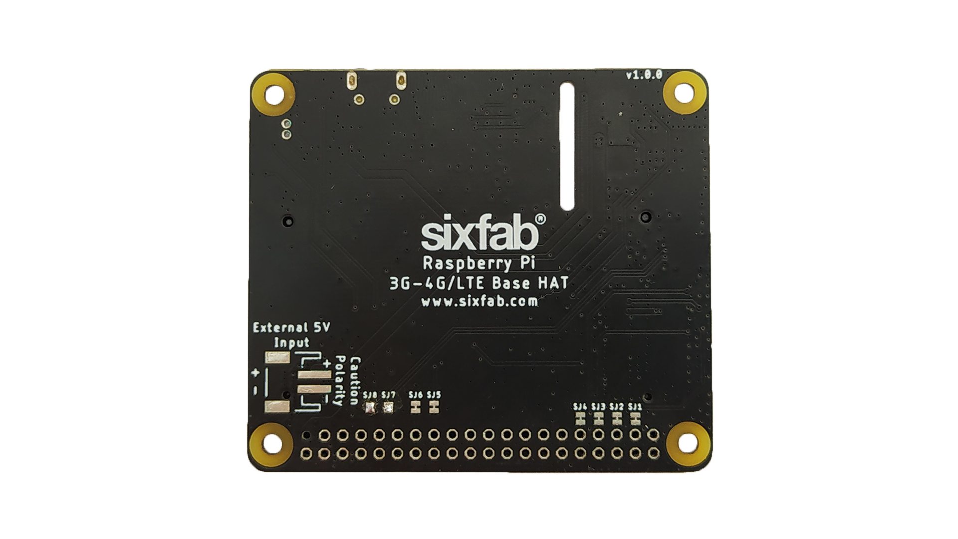
Solder Jumper(SJ)
When you observe the HAT, you will come across some solder Jumpers marked as SJx (SJ1, SJ2, SJ3, etc). These solder jumpers are either connected or disconnected by default. These can be used to enable or disable the default use case. These SJ are provided for the cases where the specific GPIO are conflicting with the users requirement. Disconnecting the jumpers may lead to loss in some programmable feature. For instance, Cutting the SJ4 trace which is RI, Ring Indicator used as indication for call or SMS cannot be used.
Disconnecting: Cut the narrow trace between the middle of these solder jumper with a utility knife.
Connecting/Reconnecting: Solder the jumper to connect the traces.
The SJ details of the HAT(v1.0.0) are mentioned below.
| Solder Jumper | Corresponding GPIO | Default State | Purpose | Affect of changing the default state | |
|---|---|---|---|---|---|
| SJ1 | GPIO26 | CONNECTED | Cut to disconnect from HAT_PWR_OFF. | Cannot control the power of the HAT. | |
| SJ2 | GPIO19 | CONNECTED | Cut to disconnect from W_DISABLE. | Cannot disable Wireless communication. | |
| SJ3 | GPIO13 | CONNECTED | Cut to disconnect DTR pin from GPIO. | Cannot use for sleep mode control. | |
| SJ4 | GPIO6 | CONNECTED | Cut to disconnect RI pin from GPIO. | Cannot read the Ring indicator. | |
| SJ5 | GPIO22 | CONNECTED | Cut to disconnect USER BUTTON | Cannot use User Button. | |
| SJ6 | GPIO27 | CONNECTED | Cut to disconnect USER LED | Cannot use User Led. | |
| SJ7 | RXD | NOT CONNECTED | Solder to connect RX of module. Used to communicate over UART. | - | |
| SJ8 | TXD | NOT CONNECTED | Solder to connect TX of module. Used to communicate over UART. | - |
USB vs UART
With Quectel mini PCIe modules, the Base HAT can be used via USB or UART. Using USB is recommended since the speed slows down via UART.
UART of the HAT is disconnected by default. In order to use the UART, the SJ7 and SJ8 needs to be soldered.
The Telit module cannot be used via UART with Base HAT. The UART will work with modules where the RX TX are at PCIe pin 11 & 13.
🔍 InfoTo use the UART follow the steps mentioned in the UART Configuration guide.
Updated 8 months ago