
Power & Mounting
Learn the power requirements and mounting options for the ALPON X4. Ensure stable operation in industrial environments.
ALPON X4 power & mounting
Power input specifications, consumption profiles, Restricted Mode behavior, and approved mounting hardware for the ALPON X4 industrial edge computer. Covers USB Type-C PD, the 9–30 V DC screw terminal, optional PoE+ on PoE-variant SKUs, and wall, DIN rail, and combined installation paths.
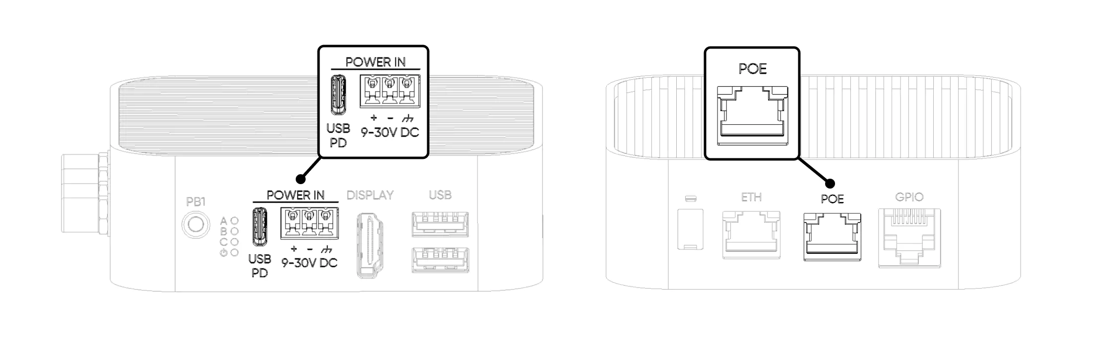
The ALPON X4 accepts power from three independent
inputs: USB Type-C PD (15 V, 27 W minimum),
a 3-pin screw terminal (9 V–30 V DC,
27 W minimum) with reverse-polarity protection, and optional
PoE+ (IEEE 802.3at, up to 25 W) on ETH/G.
All three sources share a common rail through hardware ideal diodes;
the device draws from the source with the highest voltage. Typical
consumption is 7–14 W, with a
27 W maximum. The fanless aluminum enclosure
mounts on a desk, wall, or 35 mm DIN rail via
2× 4 mm mounting holes on the base.
Power inputs
The ALPON X4 exposes three independent power interfaces. All three pass through hardware ideal diodes before joining a common system rail, so simultaneous connections are tolerated and the device always draws from the source with the highest voltage. For production deployments, use a single input at a time to simplify ground paths and failure analysis.
USB-C PD
15 V · 27 W
PD profile · bundled adapter
Sink-only USB-PD port. The bundled 27 W adapter covers every supported ALPON X4 workload.
Screw terminal
9–30 V DC
Wide range · 27 W minimum
Hardware reverse-polarity protected with a dedicated chassis ground pin. The recommended input for industrial deployments.
PoE+
37–57 V · 25 W
802.3at · ETH/G only
Single-cable install on PoE-variant SKUs. Active on ETH/G only; not retrofittable.
Hardware tolerates simultaneous connection across USB-C, the screw terminal, and PoE+, but we do not recommend using multiple sources at once in production. Simultaneous connection complicates ground paths and failure analysis.
USB Type-C PD input
The USB-C port is a sink-only USB-PD interface. It accepts power from a PD-capable adapter but does not provide USB data or power output during normal operation. The bundled 27 W adapter is sized for every supported ALPON X4 workload, including full-load operation with USB peripherals attached.
15 V / ≥1.8 A (recommended 15.0 V / 3.0 A)
CYPD3177-24LQXQ
SW2 = Burn (image flashing mode).
Powering the device between 5 V and 12 V via USB-C forces the system into Restricted Mode. High-draw subsystems (USB 2.0, GPIO Add-on 5 V rail, HDMI display output, RGB LED) are disabled to prevent brownout.
Screw terminal block (9–30 V DC)
The 3-pin screw terminal is the recommended input for industrial deployments. It accepts a wide 9–30 V DC range, includes hardware reverse-polarity protection, and provides a dedicated chassis ground pin for EMC-sensitive installations. Incorrectly wired +/− polarity will not damage the device, but the unit will not power on until corrected.
If the terminal block is powered below 12 V, the system enters Restricted Mode even though the input is nominally within the 9–30 V range. Use a 12 V or 24 V industrial supply for full functionality. For long DC cable runs, prefer a 24 V source to compensate for line drop.
Power over Ethernet (PoE+)
PoE+ is available only on PoE-variant SKUs and cannot be retrofitted — the PoE module is installed at manufacture. When present, PoE+ is wired to the ETH/G port (Gigabit Ethernet). The ETH 100 Mbps port is data-only and cannot deliver power to the system.
ETH/G only (PoE variant)
PoE+ is the preferred input for ceiling-mounted or field-deployed installations where one Cat5e/Cat6 cable carries both connectivity and power. Budget for 25 W at the PSE, accounting for cable losses on runs approaching 100 m.
Restricted Mode
Restricted Mode is a protective state the ALPON X4 enters automatically when any input drops below 12 V. It keeps the base compute and networking blocks alive on a marginal supply (down to 5 V on USB-C) while disabling the high-current peripheral rails. The device remains reachable for remote diagnostics over LTE or Ethernet, but it is not a valid operating state for production workloads — the GPIO Add-on 5 V rail, USB 2.0 ports, HDMI display output, and the programmable RGB LED are offline.
- CM4 compute module
- LTE Cat 4 modem
ETH/G(1 Gbps)ETH(100 Mbps)
- USB 2.0 ports
- GPIO Add-on port (5 V rail)
- HDMI display output
- Programmable RGB LED
Restricted Mode prevents brownouts by routing power only to the core compute and networking blocks at low input voltage. Restore 15 V USB-C PD or a 12–30 V DC supply on the terminal block, then reboot the device so the peripheral rails come back online.
Power consumption
Measured subsystem power draw at idle, 50% load, and full load. A dash (–) indicates the subsystem draws negligible standalone power at that level. Values are approximate and depend on workload, connected peripherals, and ambient temperature.
| Subsystem | Idle (W) | 50% Load (W) | Full Load (W) |
|---|---|---|---|
| CM4 Compute Module | 3 | 5 | 7 |
| LTE Modem | 1 | 2 | 3 |
| Wi-Fi / Bluetooth | – | 1 | 2.5 |
| Voltage Regulators | 1 | 1 | 2 |
| GPIO Add-on 5 V rail | – | – | 5 |
| USB 2.0 Ports | – | – | 5 |
| HDMI Display Output | – | 0.5 | 1.5 |
| Programmable RGB LED | – | 0.5 | 1 |
| Total | 5 | 10 | 27 |
A 27 W supply covers every supported ALPON X4 configuration, including PoE variants drawing from the PSE. Deployments using the GPIO Add-on port at full 5 V / 1 A draw together with USB peripherals do not require headroom above 27 W — the hardware internally arbitrates rail budgets.
Mounting
The ALPON X4 enclosure includes 2× 4 mm mounting holes on its base for direct attachment to walls, panels, or DIN rail adapters. The fanless aluminum case doubles as a passive heatsink, so mounting orientation should preserve airflow across the top finned surface. Three mount kits are supported: wall, DIN rail, and a combined adapter.
Wall mount
Steel L-bracket fastened to the device with 2× M4 screws. Suits drywall, plywood, and sheet-metal surfaces.
DIN rail
Clip-on adapter for any 35 mm top-hat rail (EN 60715). Mounts the device into standard industrial racks.
Combined
Wall bracket layered with the DIN rail adapter. Switch between surface and rail mounting without re-fastening.
Keep at least 30 mm clearance above the top cooling surface and avoid airtight cabinets when running sustained workloads above +40 °C ambient. Mounting horizontally (top face up) maximizes convective heat dissipation.
Wall mount installation
The wall mount kit ships with all fasteners required for drywall, plywood, or metal panel surfaces. Use the supplied wall plugs for masonry and the lock nuts for panel through-mounting.
Mark the wall
Position the bracket on the wall, mark the two screw hole locations with a pencil, and confirm the bracket is level.
Drill pilot holes
Drill the marked holes to match the supplied 8 mm wall plugs. For metal panels, drill to the screw diameter and omit plugs.
Insert the wall plugs
Press the plugs flush with the wall surface before driving screws.
Attach the bracket to the device
Align the bracket with the 2× 4 mm mounting holes on the base of the ALPON X4. Secure using the M4×6 mm Phillips pan-head screws.
Mount the assembly to the wall
Position the bracket over the wall plugs and drive the M5.5×45 mm sheet-metal screws until the assembly is flush and stable.
DIN rail installation
The DIN rail adapter attaches directly to the base of the ALPON X4 and snaps onto any standard 35 mm top-hat DIN rail (EN 60715). Use this method for control cabinets, industrial panels, or any rack where multiple ALPON X4 units need uniform spacing.
Align the adapter
Place the DIN rail adapter against the base of the ALPON X4 so its screw holes line up with the device's 2× 4 mm mounting holes.
Fasten the adapter
Drive the two M4×6 mm Phillips pan-head screws to secure the adapter to the enclosure.
Snap onto the rail
Hook the upper clip of the adapter over the top edge of the DIN rail, then press the lower section until it clicks into place.
Combined wall + DIN rail mount
The combined option layers the DIN rail adapter on top of the wall mount bracket. Useful when a deployment may migrate between surface-mounted and panel-mounted installations without replacing fasteners.
Install the wall mount first
Follow the wall mount steps above to attach the bracket to the device.
Layer the DIN rail adapter
Position the DIN rail adapter over the wall bracket and align its mounting holes.
Secure the assembly
Fasten the adapter to the wall bracket using the supplied screws.
Deploy on rail or wall
Slide the complete assembly onto a DIN rail, or fix the wall bracket backplate directly to a flat surface.
Mechanical envelope
Key physical parameters relevant to mount planning and thermal design.
Power troubleshooting
Common power-related issues and resolution steps. If symptoms persist after these checks, contact Sixfab support with the cable type, supply voltage, and observed LED state.
The device does not power on
- Confirm the supply voltage matches the input you are using: 12 V or 15 V PD profile for USB-C, 9–30 V DC for the terminal block, or a compliant 802.3at PSE for PoE+.
- On the screw terminal, verify polarity. Pin 2 is negative (−) and Pin 3 is positive (+). Reverse polarity will not damage the device but prevents power-on.
- For PoE+, confirm the cable is plugged into
ETH/G. TheETH100 Mbps port does not accept PoE. - Check the power LED. If it flickers briefly then drops, the supply is current-limited below the 27 W minimum.
The device boots but USB, GPIO, or HDMI are unavailable
- The device has entered Restricted Mode. Check the supply voltage at the active input. Any reading below 12 V triggers protection.
- Replace the adapter with a PD-capable unit that negotiates at 15 V, or switch to the terminal block with a 12 V or 24 V industrial supply.
- Reboot the device after restoring a compliant source so the peripheral rails come back online.
The device resets under load
- Measure total draw when LTE, USB peripherals, and the GPIO 5 V rail are all active. If consumption approaches 27 W, swap cables and adapters for ones rated above the minimum.
- Check cable quality for USB-C. Non-compliant USB-C cables can drop voltage under sustained load even with a capable adapter.
- For PoE+, verify the cable run length. Cable losses on 100 m runs can bring delivered power below the 25 W port budget.
Updated 13 days ago