Technical Details
This section introduces the concepts and terms that are crucial for the understanding, implementation and use of NVIDIA Jetson Nano 4G/LTE Cellular Modem Kit
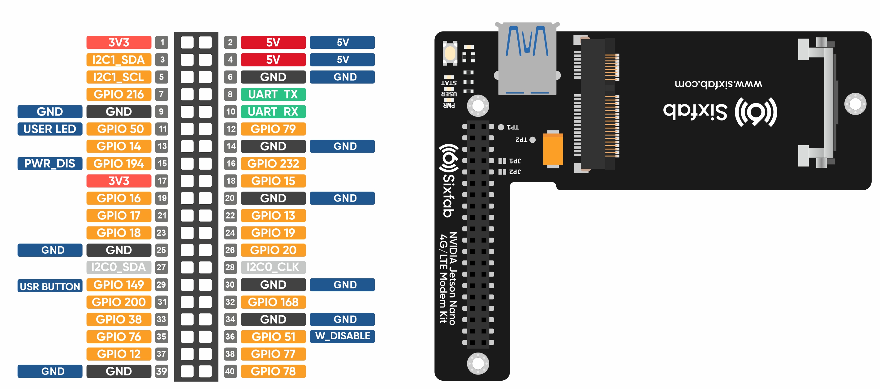
Pinout

Pin Descriptions
| Pin Number | Linux GPIO | Pin Name | Description |
|---|---|---|---|
| 11 | GPIO50 | USER LED | Active HIGH, to switch on the USER LED, the pin's state should be HIGH. |
| 29 | GPIO149 | USER BUTTON | This pin normally pulled-down to ground. When the button is pressed, pin switches to LOW. |
| 36 | GPIO51 | W_DISABLE | This pin is used to turn Airplane Mode on the module, by pulling it HIGH. |
| 15 | GPIO194 | PWR_DIS | Power regulator control. Normally pulled-down, when this pin drove to HIGH, Hat's power will cut off. |
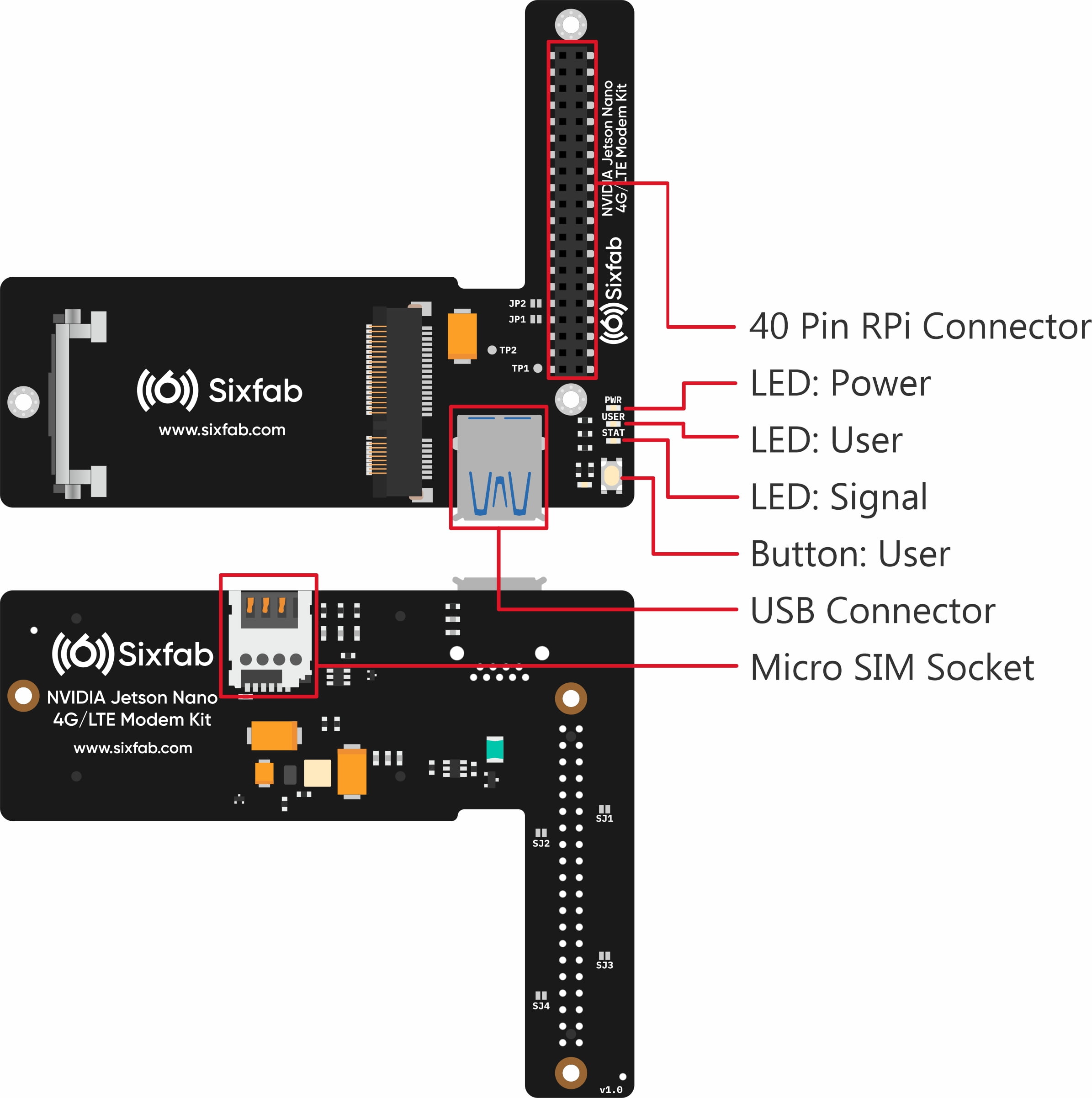
Layout

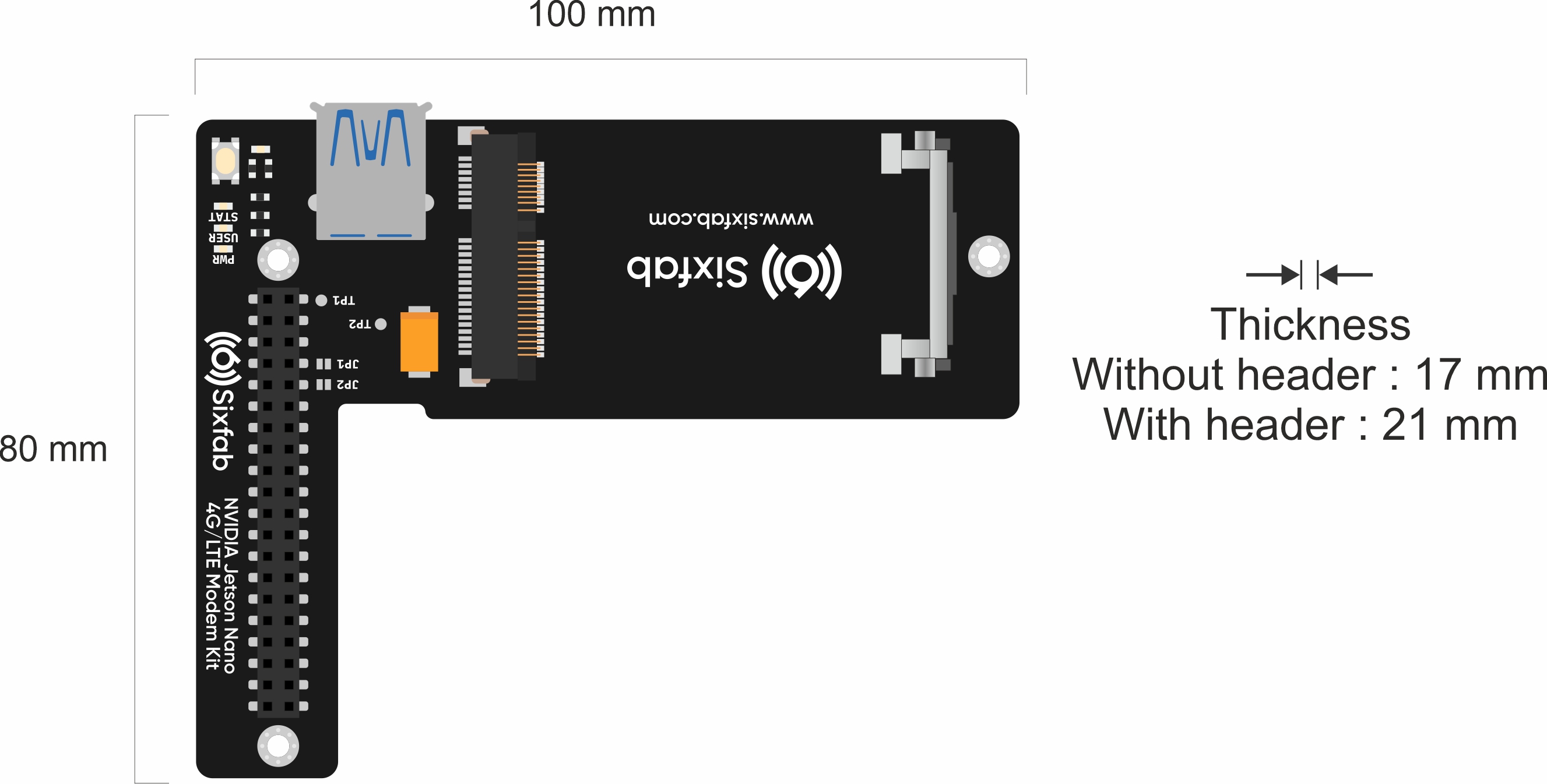
Dimension

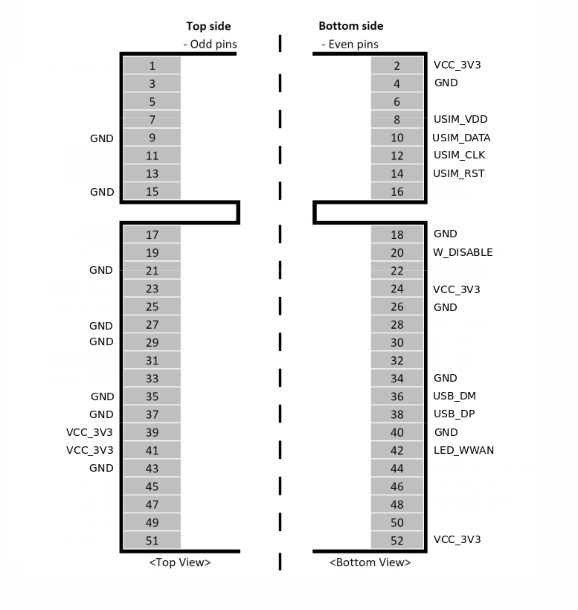
Compatible Mini PCIe Modules
If one is looking to use different mini PCIe modules other than the ones mentioned below, it should be compared with the pinout of mini PCIe below. The following mentioned pins are connected to the Jetson Nano HAT.
The minimum requirement is to match VCC_3V3, GND, USIM_VDD, USIM _DATA, USIM_CLK, USIM_RST, USB_DM & USB_DP

Power
When you use the Cellular Modem Kit with Jetson Nano, you must use a good power supply. Jetson Nano already needs a lot of power with its powerful features. Add to that LTE Connectivity, if you don't use a good power supply you will have problems.
Strongly Recommend
- On 4GB Jetson Nano sets, power the system with an adapter that can provide min 5V 4A power from the Power Jack (J25) input.
- Do not use micro USB socket for power in both 4GB and 2GB versions. Micro USB Connector power capacity is very low.
- In the 2GB Version, when powering via Type C connector, do not only power over PC USB or a simple phone charger adapter. Use an adapter that can provide a minimum of 5V 3A.
LEDs
- PWR LED: When the module is powered up, this RED led turns on
- STAT LED: This BLUE led indicates the status of the connection. When the connection is established and data is being transmitted/received, this led will blink at special intervals. Otherwise, if there is no connection, the led will remain off.
- USER LED: It is a programmable user-led can be controlled from the GPIO50 of Jetson Nano for debugging or just fun.
Buttons
- User Button: It is a programmable user button that is connected to GPIO149. It reads HIGH by default.
Solder Jumper(SJ)
When you observe the HAT, you will come across some solder Jumpers marked as SJx (SJ1, SJ2, SJ3, etc). These solder jumpers are either connected or disconnected by default. These can be used to enable or disable the default use case. These SJ are provided for the cases where the specific GPIO are conflicting with the users requirement. Disconnecting the jumpers may lead to loss in some programmable feature.
- Disconnecting: Cut the narrow trace between the middle of these solder jumper with a utility knife.
The SJ details of the HAT(v1.0) are mentioned below.
| Solder Jumper | Corresponding GPIO | Default State | Purpose | Affect of changing the default state |
|---|---|---|---|---|
| SJ1 | GPIO50 | CONNECTED | Cut to disconnect USER LED | Cannot use user LED. |
| SJ2 | GPIO194 | CONNECTED | Cut to disconnect from HAT_PWR_OFF | Cannot control the power of the HAT. |
| SJ3 | GPIO149 | CONNECTED | Cut to disconnect USER BUTTON | Cannot use user button. |
| SJ4 | GPIO51 | CONNECTED | Cut to disconnect from W_DISABLE | Cannot disable wireless communication. |
Specifications
Quectel EG25-G LTE Cat 4 Mini PCIe Module | |
|---|---|
Region | Global |
Frequency Bands |
|
Regulatory | GCF, CE , UKCA, PTCRB, FCC, IC, Anatel, IFETEL, KC, NCC, JATE/TELEC, RCM, ICASA |
Data
LTE
• LTE-FDD: Max. 150 Mbps downlink/Max. 50 Mbps uplink
• LTE-TDD: Max. 130 Mbps downlink/Max. 30 Mbps uplink
UMTS
• DC-HSDPA: Max. 42 Mbps downlink
• HSUPA: Max. 5.76 Mbps uplink
• WCDMA: Max. 384 kbps downlink/Max. 384 kbps uplink
GSM
• EDGE: Max. 296 kbps downlink/Max. 236.8 kbps uplink
• GPRS: Max. 107 kbps downlink/Max. 85.6 kbps uplink
GNSS
GPS/GLONASS/BDS/Galileo/QZSS (Optional)
Environmental
Operating Temperature Range: -35 to +75 °C
Extended Temperature Range: -40 to +80 °C
Reports, and Other Resources
Updated 3 months ago
