Technical Details
This section introduces the concepts and terms that are crucial for the understanding, implementation and use of Raspberry Pi 5G Development Kit
Pinout
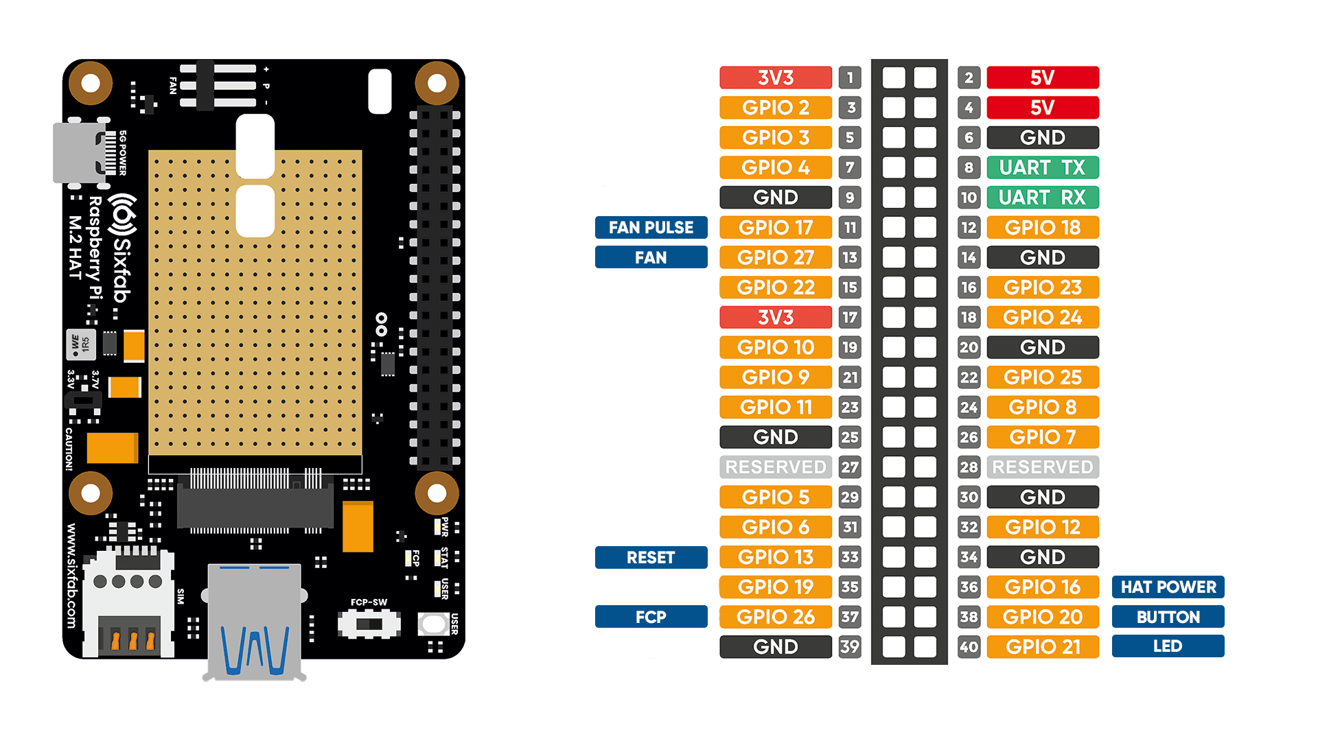
Pin Descriptions
| Pin Number | BCM Pin | Pin Name | Description |
|---|---|---|---|
| 11 | GPIO17 | F-PULSE | This pin functions to check if the FAN is working. |
| 13 | GPIO27 | FAN | This pin is used to turn on the FAN by pulling HIGH. It is LOW by default. |
| 33 | GPIO13 | MODULE_RESET | By pulling this pin HIGH, the module is reset. It should be pulled to LOW shortly after pulling HIGH. |
| 37 | GPIO26 | FCP_OFF_N | By pulling the Full Card Power (FCP) pin to HIGH, the module will start and boot. |
| 40 | GPIO21 | USER_LED | Active HIGH, to switch on the USER LED, the pin's state should be HIGH. |
| 38 | GPIO20 | USER_BUTTON | This pin normally pulled-down to ground. When the button is pressed, pin switches to LOW. |
| 36 | GPIO16 | PWR_DSBLE_P | Power regulator control. When this pin is pulled HIGH, the HAT will be powered off except for the FAN. |
Layout
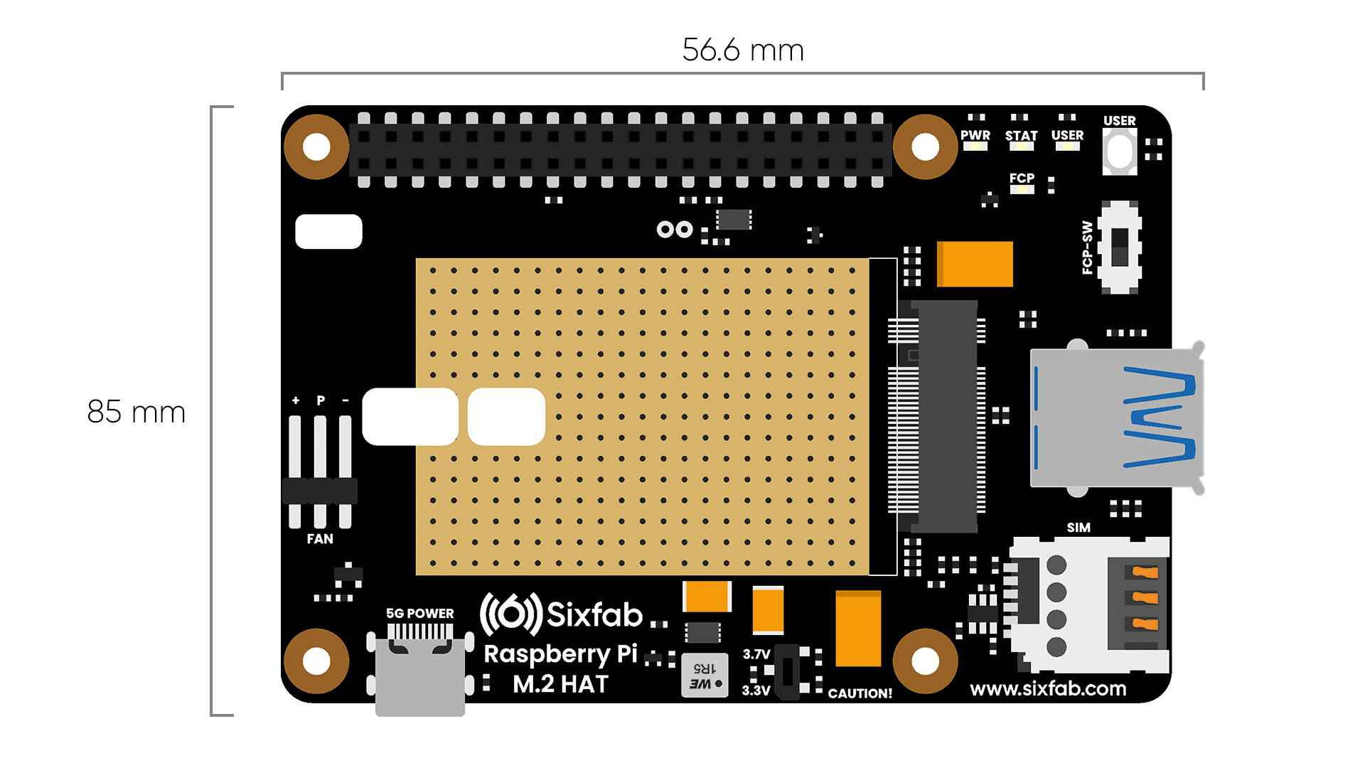
Dimension
Compatible M.2 Modules
The following table includes the M.2 modules there were tested. For other M.2 modules check the details under the table.
| Manufacturer | Module |
|---|---|
| Quectel | RM50xQ |
| Telit | FN980 |
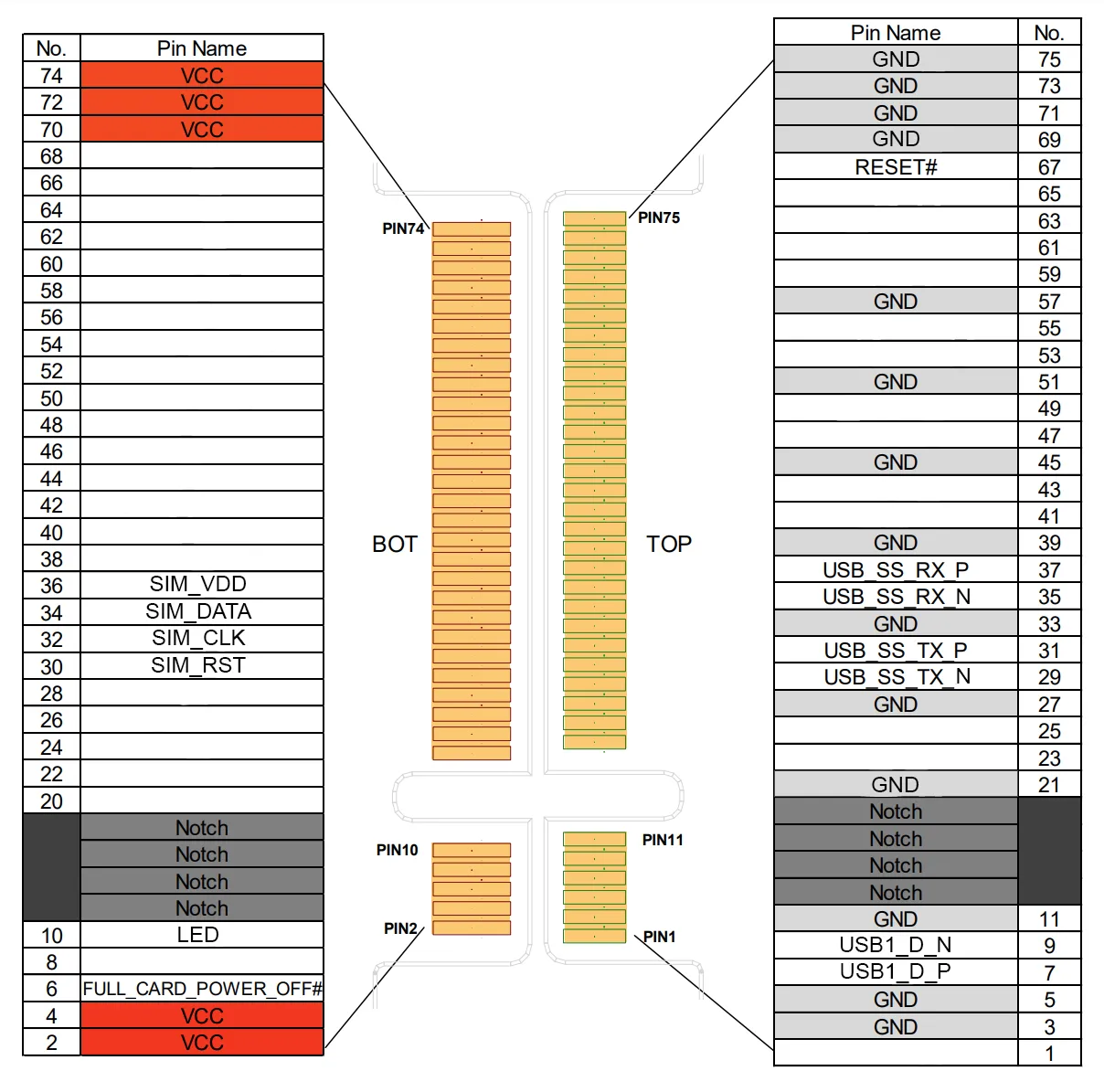
- If one is looking to use different M.2 modules other than the ones mentioned above, it should be compared with the pinout of M.2 below. The following figure shows the pin assignment of the Sixfab M.2 5G HAT. Make sure the module pin assignment has common pins compared to the following pin assignment.
Power
Rated input voltage(V): 5V DC
Rated input current(A): 3.0A
Power Adapter
A separate power adapter for the HAT is required. Connect the Sixfab Power Adapter that comes with the kit to the HAT, additionally to the power supply of Raspberry Pi
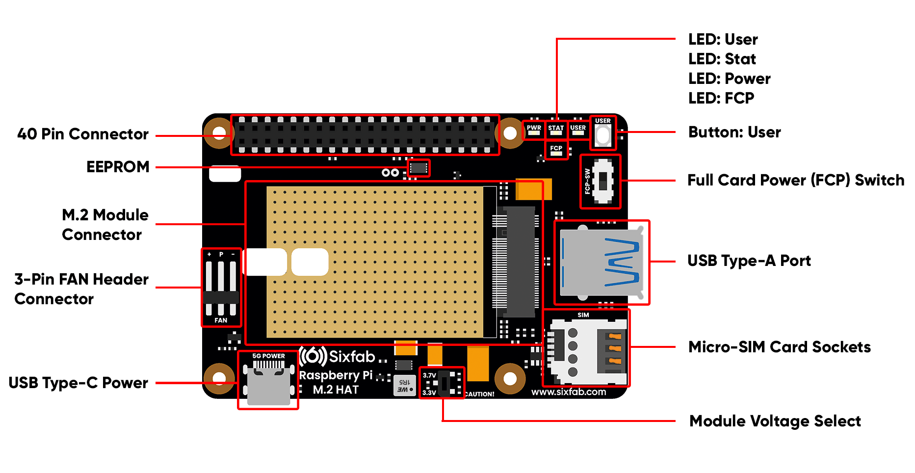
Module Voltage Select
The ideal operating voltages of 5G modules are different. That's why HAT is designed with adjustable voltage output.
Before installing the module you will use, please check the operating voltage from the datasheet of the module and set the switch to the appropriate position.
The operating voltages of commonly used 5G modules are given below.
- Quectel: 3.7V
- Telit: 3.3V
Module Power ON/OFF
There are two methods to turn the module on and off.
- Physically: Set the FCP switch to the ON/OFF position.
- Software: Drive the Raspberry Pi GPIO26 pin to HIGH(ON)/LOW(OFF).
You can find out if the module is on by checking the FCP LED. It will light up when the module is on.
On average, it takes more than 30 seconds for the modules to fully boot up.
FAN
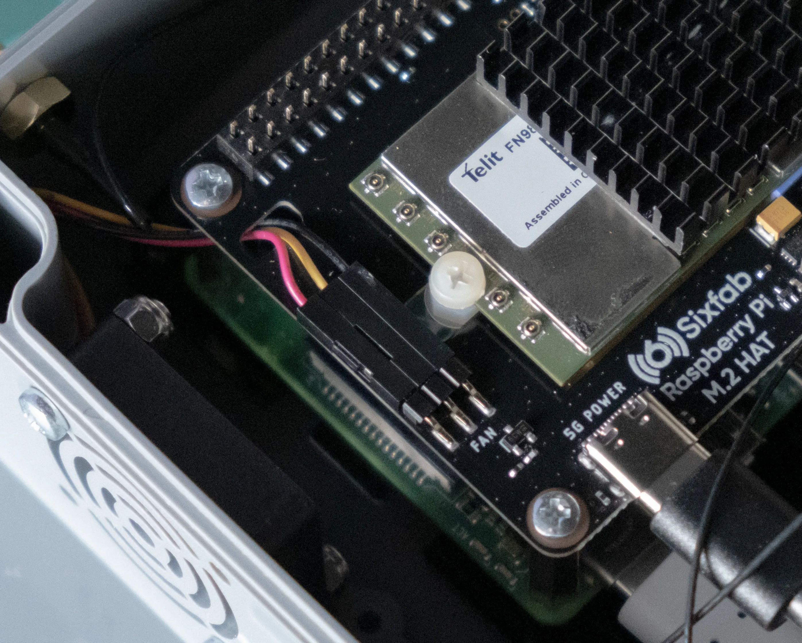
To activate the FAN, after making the cable connections as in the picture below, the Raspberry Pi GPIO27 must be set to HIGH.
LEDs
- PWR LED: This LED lights RED when 3.3V/3.7V power is supplied to the HAT.
- STAT LED: This BLUE led indicates the status of the connection. When the connection is established and data is being transmitted/received, this LED will blink at special intervals. Otherwise, if there is no connection, the LED will remain off.
- USER LED: It is a programmable user-led can be controlled from the GPIO21 of Raspberry Pi for debugging or just fun.
- FCP LED: This LED indicates FCP pin status.
Buttons
- User Button: It is a programmable user button that is connected to GPIO20. It reads HIGH by default.
Solder Jumper(SJ)
When you observe the HAT, you will come across some solder Jumpers marked as SJx (SJ1, SJ2, SJ3, etc). These solder jumpers are connected by default. These can be used to enable or disable the default use case. These SJ are provided for the cases where the specific GPIO are conflicting with the user's requirement. Disconnecting the jumpers may lead to loss in some programmable feature.
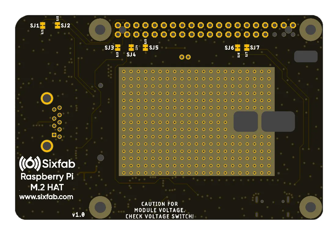
The SJ details of the Sixfab Raspberry Pi M.2 5G HAT(v1.0) are mentioned below.
| Solder Jumper | Corresponding GPIO | Default State | Purpose | Affect of changing the default state |
|---|---|---|---|---|
| SJ1 | GPIO20 | CONNECTED | Cut to disconnect from USER_BUTTON | Cannot use User Button. |
| SJ2 | GPIO21 | CONNECTED | Cut to disconnect from USER_LED | Cannot use User LED. |
| SJ3 | GPIO26 | CONNECTED | Cut to disconnect from FCP_OFF_N | FCP_OFF_N pin cannot be used. |
| SJ4 | GPIO16 | CONNECTED | Cut to disconnect from PWR_DSBLE_P | PWR_DSBLE_P pin cannot be used. |
| SJ5 | GPIO13 | CONNECTED | Cut to disconnect from MODULE_RESET | MODULE_RESET pin cannot be used. |
| SJ6 | GPIO27 | CONNECTED | Cut to disconnect from FAN | FAN can't work. |
| SJ7 | GPIO17 | CONNECTED | Cut to disconnect from F-PULSE | The FAN working status cannot be controlled. |
Specifications
The specifications of Quectel RM502Q-AE, which is the module that comes with the kit, are as follows. For other modules, please check the datasheet of the module.
Quectel RM502Q-AE M.2 5G Sub-6 Module | |
|---|---|
Region | Global (Except for China) |
Supply Voltage Range | 3.135–4.4 V, typical 3.7 V |
Frequency Bands | 5G NR
|
Regulatory | GCF/ CE/ PTCRB/ FCC/ IC/ JATE/ TELEC/ RCM |
Data
The presented data rates(max.) are theoretical only, and the actual value depends on network conditions.
5G
• 5G SA Sub-6: Downlink 4.2 Gbps; Uplink 450 Mbps
• 5G NSA Sub-6: Downlink 5.0 Gbps; Uplink 600/650 Mbps
LTE
Downlink 2.0 Gbps; Uplink 200 Mbps
WCDMA
Downlink 42 Mbps; Uplink 5.76 Mbps
GNSS
GPS/GLONASS/BeiDou(Compass)/Galileo
Updated 2 months ago
