
Quickstart
From unboxed kit to first inference on the Sixfab Edge AI Expansion Board
Assemble the under-board stack, enable PCIe Gen 3 in config.txt,
install the DEEPX runtime, and verify the NPU before running your first
inference. End to end, around 30 minutes once the M.2 modules are on hand.
Intelligented by DEEPX. Built on Raspberry Pi.
Before you start
This Quickstart is one of three paths through the Edge AI Expansion Board documentation. Pick the one that matches what you want to build. You can always come back here when you need the runtime up and running.
The procedure
Six steps. Step 1 checks the prerequisites, steps 2 to 4 set up the hardware, OS, and software stack, step 5 verifies the NPU, and step 6 runs your first inference. Work through them in order.
Check the prerequisites
The Edge AI Expansion Board is an under-board baseboard for Raspberry Pi 5. Confirm the host platform and the M.2 modules you need are on hand before you open the antistatic bag.
What you need
run_hello_world detection demo. The demo also runs against a stored video file if no camera is connected.
What's in the box
The kit ships ready to assemble. All spacers, screws, the PCIe FFC cable, and the passive cooler ship in the same box.
M.2-PCIE slot during assembly (Step 2). The AI accelerator the rest of this guide brings up.
Raspberry Pi 5, the other labelled Edge AI.
Assemble the under-board stack
The Expansion Board sits underneath the Raspberry Pi 5. You install the spacers, connect the 40 mm PCIe FFC cable to the Expansion Board, mount the Raspberry Pi 5 on top so its pogo pins make contact, seat the AI module and its passive heatsink, connect the FFC to the Raspberry Pi 5 and seat the USB Bridge, then finish with the underside modules. Pogo pins on the Expansion Board top side back-power the Raspberry Pi 5 through the GPIO header's 5V and GND pins.
The Expansion Board is not hot-pluggable. Disconnect the USB-C power supply completely before installing or removing the Expansion Board or any M.2 module. Mounting under power can damage the DEEPX silicon or the Raspberry Pi 5.
Three M.2 slots, three jobs
Each slot is labelled on the silkscreen. The AI accelerator goes in
M.2-PCIE only; the other two slots host storage and cellular over the
internal USB hub.
/dev/sda. Use one of the included
M.2 module spacers between the SSD and the board.
Assembly order
Each step below pairs the instruction with the matching animation, so the orientation and seating cues are visible right where you need them.
- Install the spacers. Screw the 6× M2.5 female-female 16 mm
spacers into the bottom side of the Expansion Board as the base
standoffs. On the top side (the side with the M.2 slots), fit
the 2× M2.5 × 5 mm plastic screws and the 4× M2.5 × 5 mm male-female spacers,
one in each corner mounting hole.
Fig. 1 6× M2.5 16 mm female-female standoffs on the bottom side; 2× M2.5 × 5 mm plastic screws and 4× M2.5 × 5 mm male-female spacers on the top side. - Connect the PCIe FFC cable to the Expansion Board. Insert the
cable into the PCIe FFC connector on the Expansion Board with the
EDGE AIlabel facing up. Align the Pin 1 marking, fully insert, and close the latch. Do this before mounting the Raspberry Pi 5; with the Raspberry Pi 5 in place, the board-side FFC connector is harder to reach.
Fig. 2 Seat the PCIe FFC with the EDGE AIlabel facing up, Pin 1 aligned, latch closed. - Mount the Raspberry Pi 5. Before mounting, make sure you have
flashed Raspberry Pi OS to the microSD card and inserted the card into the
Raspberry Pi 5. Once the PCIe FFC cable is connected to the Raspberry Pi 5,
the microSD card cannot be removed without disconnecting the cable. Then lower the
Raspberry Pi 5 onto the 4× 5 mm male-female spacers so the pogo pins on the Expansion
Board's top side line up with and contact the underside pads of the Raspberry Pi 5
GPIO header (two 5V pads and two GND pads). Secure the Raspberry Pi 5 with
4× M2.5 × 5 mm plastic screws.
Fig. 3 microSD card flashed and inserted first; lower the Raspberry Pi 5 onto the 4× 5 mm spacers with the pogo pins aligned, then secure with 4× M2.5 × 5 mm plastic screws. - Install the DEEPX DX-M1 AI module. Insert the AI module into the
M.2-PCIEslot at a 30° angle and fully seat the gold contacts. Place the M.2 module spacer at the far mounting hole, press the module flat, then secure it with the module screw.
Fig. 4 Seat the DEEPX DX-M1 in the M.2-PCIEslot at 30°, add the M.2 module spacer, and fasten with the module screw. - Attach the passive heatsink (recommended). The kit
includes a passive heatsink for the DEEPX DX-M1 M.2 AI Module. Fitting it keeps
the NPU cooler under sustained inference, so it is recommended for most workloads.
Place the heatsink on the module as shown below and press down gently and evenly
so it makes full contact.
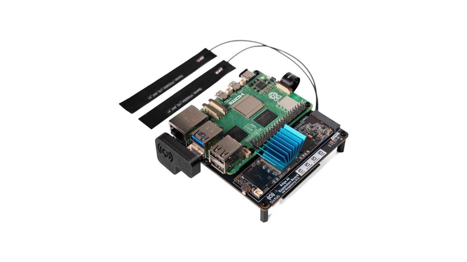
Fig. 5 The passive heatsink attached to the DEEPX DX-M1 M.2 AI Module, pressed flat so it makes full contact. - Connect the FFC to the Raspberry Pi 5 and seat the USB Bridge.
Insert the
RPi5end of the PCIe FFC cable into the Raspberry Pi 5's PCIe socket and close the latch. On the other side, seat the USB Bridge daughterboard, which routes the internal USB hub (the data path for the NVMe and cellular slots) to the Raspberry Pi 5. The Sixfab logo on the USB Bridge must face outward and sit flat.
Fig. 6 Seat the RPi5end, close the latch, fit the USB Bridge with the Sixfab logo facing out and flat. - Install the underside modules. Turn the board over to its
underside. Insert the LTE/5G modem into the
CELLULAR LTE/5Gslot and secure it with the M2 × 4 mm flat-head screw. Insert the NVMe SSD into theM.2-USBslot, place an M.2 module spacer, and secure it with the module screw. Insert a nano SIM into the SIM slot. Each M.2 module goes in at a 30° angle with the gold contacts fully seated.
Fig. 7 LTE/5G modem in CELLULAR LTE/5G(M2 × 4 mm screw), NVMe SSD inM.2-USB(with M.2 module spacer and screw), and the nano SIM. - Power the system. Connect the USB-C PD adapter to the
Type-C socket on the Expansion Board; this powers the whole stack and
back-powers the Raspberry Pi 5 through the pogo pins. Fit the included Type-C cap onto
the Raspberry Pi 5's own USB-C port so no one accidentally powers the Pi from there.
The stack is now ready for first boot and driver install.
Fig. 8 Connect the USB-C PD adapter to the Expansion Board's Type-C socket, and cap the Raspberry Pi 5's own USB-C port to prevent dual-powering.
Finger-tight is the spec. Loose spacers cause intermittent pogo-pin contact, which shows up as power glitches or reboots under load. Over-torquing strips the threads in the spacers and the threads are not field-repairable. No power driver.
The cable has two distinct ends. The end labelled Raspberry Pi 5 goes to
the Raspberry Pi 5's PCIe port; the end labelled Edge AI goes to
the Expansion Board's PCIe port. Match the Pin 1 arrow on each end to the
corresponding marking on the PCB connector. A reversed or partially seated
cable produces no PCIe link, and the DX-M1 will not enumerate on
lspci.
The cable is a 40 × 8.5 mm FFC designed by Sixfab and is included in the box. A longer cable or a different pitch is not recommended.
Configure /boot/firmware/config.txt and power on
Up to three lines need to be in /boot/firmware/config.txt before the
DEEPX runtime is installed: one to enable the Raspberry Pi 5's PCIe lane, one to set it to
Gen 3, and one to lift the USB current limit, which is needed only if you boot
the Raspberry Pi 5 from the NVMe SSD. When booting normally from the microSD
card, the third line is not needed.
Power on the Raspberry Pi 5 (USB-C PD supply connected to the Expansion Board's
USB-C port; the Expansion Board back-powers the Raspberry Pi 5), wait for it to boot to a
terminal, then add the lines below to the end of /boot/firmware/config.txt.
# 1. Open config.txt in your editor of choice
sudo nano /boot/firmware/config.txt

# 2. Append these lines at the end of the file:
dtparam=pciex1
dtparam=pciex1_gen=3

# Only if booting from the NVMe SSD (USB boot); not needed for microSD boot:
usb_max_current_enable=1

# 3. Save (Ctrl+O, Enter) and exit (Ctrl+X), then reboot
sudo reboot
What each line does
dtparam=pciex1: enables the Raspberry Pi 5's external PCIe x1 lane that the 40 mm FFC cable routes to the DX-M1.dtparam=pciex1_gen=3: pushes the PCIe link from Gen 2 (the safe default on Raspberry Pi OS) to Gen 3. The DX-M1 supports Gen 3, and measured bandwidth jumps from 400–450 MB/s at Gen 2 to 800–900 MB/s at Gen 3.usb_max_current_enable=1: lifts the Raspberry Pi 5's USB current cap. Only needed when booting from the NVMe SSD (USB boot): without it, the Raspberry Pi 5 pauses at boot and prompts the user to press the on-board button to acknowledge that more than 1.6 A of USB current is being requested. When booting from the microSD card, this line is not required.
A power supply under 27 W triggers reduced system performance and an on-screen under-voltage warning. Symptoms include SSD disconnects and random reboots. The official Raspberry Pi 27 W USB-C PSU is the documented minimum; for a full-stack configuration with AI + NVMe + LTE/5G, a 45 W supply is strongly recommended.
The Sixfab APT package installs the kernel driver and runtime, but it does
not edit config.txt on the user's behalf. Adding these lines
before the install means the next reboot brings PCIe Gen 3 up cleanly and the
DX-M1 enumerates at full speed on first boot.
Install the driver and DEEPX runtime
The sixfab-dx APT package installs the kernel driver (via DKMS),
the DEEPX runtime (dxrt-runtime), and the CLI tools
(dxrt-cli, dxtop, run_hello_world). It also
pulls in raspberrypi-kernel-headers automatically so the DKMS build
succeeds. First add the Sixfab APT repository (apt-repo-sixfab), then
install the runtime.
# 1. Add the Sixfab APT repository
sudo apt update
sudo apt install apt-repo-sixfab
# 2. Refresh the index and install the driver + DEEPX runtime
sudo apt update && sudo apt install sixfab-dx
When the installer prompts Do you want to continue? [Y/n], type
Y and press Enter. The driver compiles against your running
kernel via DKMS, so the first install can take 5–10 minutes depending on
connection speed and CPU.
The package downloads the runtime and pulls kernel headers from the Pi OS repositories. After install, the board can run fully offline; AI inference does not need an internet connection.
Because the driver is built through DKMS, it normally rebuilds automatically
when the kernel changes. If after a major OS update the NPU stops appearing,
run lsmod | grep -i dx. If nothing matching dx_dma
is loaded, reinstall the package with sudo apt install --reinstall
sixfab-dx to rebuild the module against the new kernel.
Verify the NPU
Before running the first inference, confirm the DX-M1 is up with a single command. Detailed status checks and per-subsystem setup live on their dedicated pages, linked below.
dxrt-cli -s
Prints the runtime, driver, and firmware versions, the PCIe link speed, and per-core status. Full NPU status checks and health monitoring are covered on the System Monitoring page.
AlwaysInstalled the NVMe SSD? Partitioning, mounting, and verification are covered step by step on the NVMe Storage page.
If NVMe installedInstalled the LTE/5G modem? The data connection is not configured yet at this point; setup and verification are covered on the Cellular Connectivity page.
If modem installedRun your first inference on the NPU
The sixfab-dx package ships with a pre-compiled YOLOv8 detection
demo wired up to run_hello_world. A single command launches it on the
DEEPX NPU and opens a window with bounding boxes drawn in real time.
run_hello_world
A window opens showing the live feed (camera or stored video) with bounding boxes drawn around detected objects in real time.
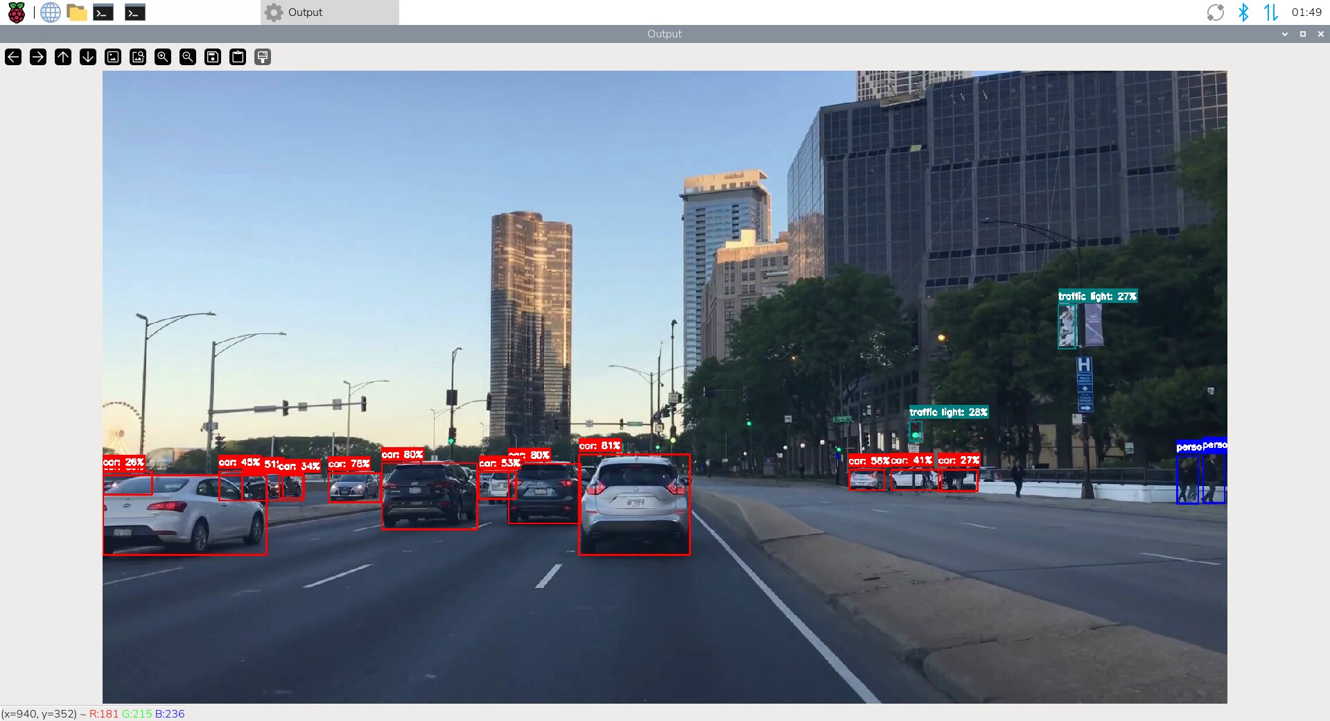
A live detection window means YOLOv8 is executing on the DEEPX NPU, not on the Raspberry Pi CPU. That's the Edge AI Expansion Board doing its job, with zero load on the Raspberry Pi 5's ARM cores. Concurrent NVMe writes and LTE/5G traffic do not measurably degrade this throughput.
Watch the NPU work in real time
Open a second terminal while the demo is running and launch dxtop.
It prints per-core utilisation, voltage, clock, and temperature, much like
htop for the NPU.
dxtop
Press q to quit. The DX-M1 begins thermally throttling at
approximately 90 °C; sustained inference well below that is the goal, and
dxtop is how you watch for it. The full set of monitoring tools and
how to plug them into production fleets is documented separately in
System Monitoring.
All AI inference happens on-device. There is no outbound data flow unless
you build one into your application. If you also installed the NVMe SSD,
run_hello_world does not write to it by default; logging inference
results to the NVMe is something your application configures explicitly.
Where to next
YOLOv8 is now running on the DEEPX NPU. The hardware, OS, and runtime stack are healthy, and the next chapter is AI Model Deployment: choose more pre-compiled models, bring your own trained model to the NPU, or instrument the deployment for production.
dxrt-cli and dxtop. Read NPU telemetry, surface
it to dashboards, and watch deployments in real time.
Monitor the NPU →
Updated 20 days ago