
Technical Details
This section introduces the concepts and terms that are crucial for the understanding, implementation and use of Pico LTE.
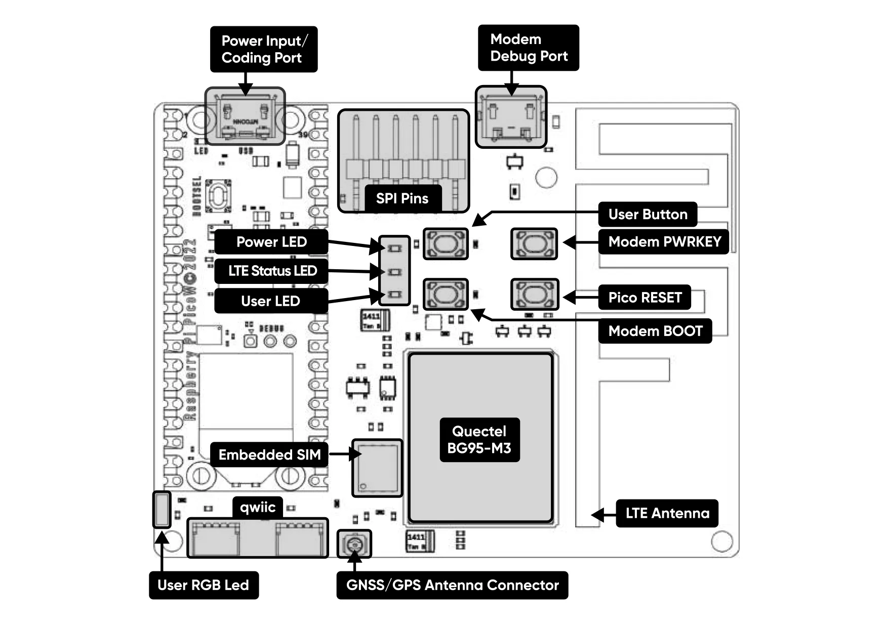
Layout
Pinout
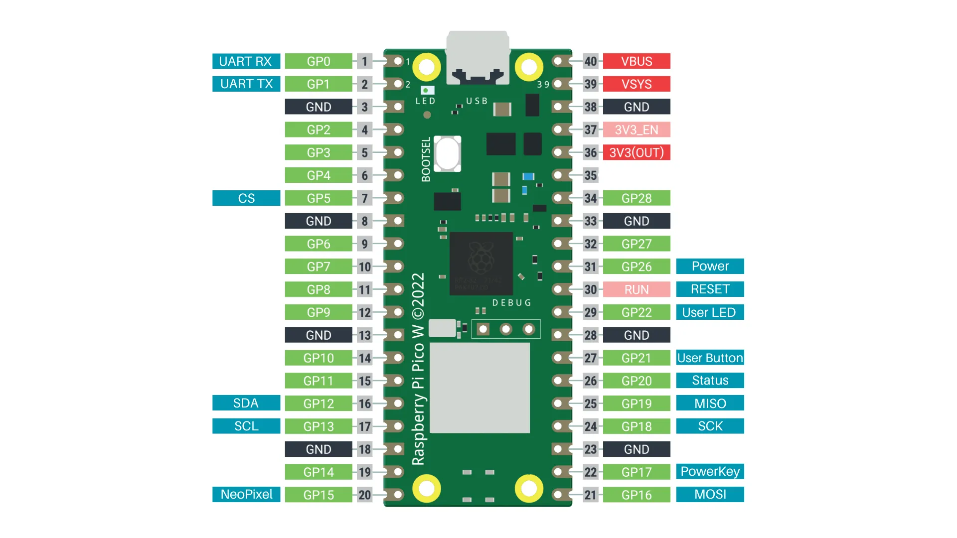
Pin Descriptions
| Pin Number | BCM Pin | Pin Name | Description |
|---|---|---|---|
| 1,2 | GP0, GP1 | UART | It is connected to the UART pins of the BG95 module and is used for UART communication. |
| 26 | GP20 | Status | It indicates the on/off status of the BG95 module. The pin is in the LOW position when the module is turned on. |
| 22 | GP17 | PowerKey | When this pin toggles from LOW to HIGH for a second the module will turn on if it was off and vice versa. |
| 31 | GP26 | Power | By default, it is in the LOW position, supplying power to the module. If set to HIGH, the module's power is cut off. |
| 16,17 | GP12, GP13 | Qwiic I2C | The two parallel-connected Qwiic sockets on the Pico LTE are connected to these pins for I2C communication. |
| 7, 21, 24, 25 | GP5,GP16, GP18,GP19 | SPI | External access is provided to the SPI pins on the Pico LTE. |
| 20 | GP15 | NeoPixel LED | The NeoPixel LED is controlled using this pin. |
| 27 | GP21 | User Button | This pin is pulled to the default HIGH state. When the button is pressed, the pin is pulled to the LOW. |
| 29 | GP22 | User LED | When the pin is pulled HIGH, the LED lights up. |
| 30 | RUN | Pico W Reset | This pin is connected to the RESET button. When the button is pressed, it resets the Raspberry Pi Pico W. |
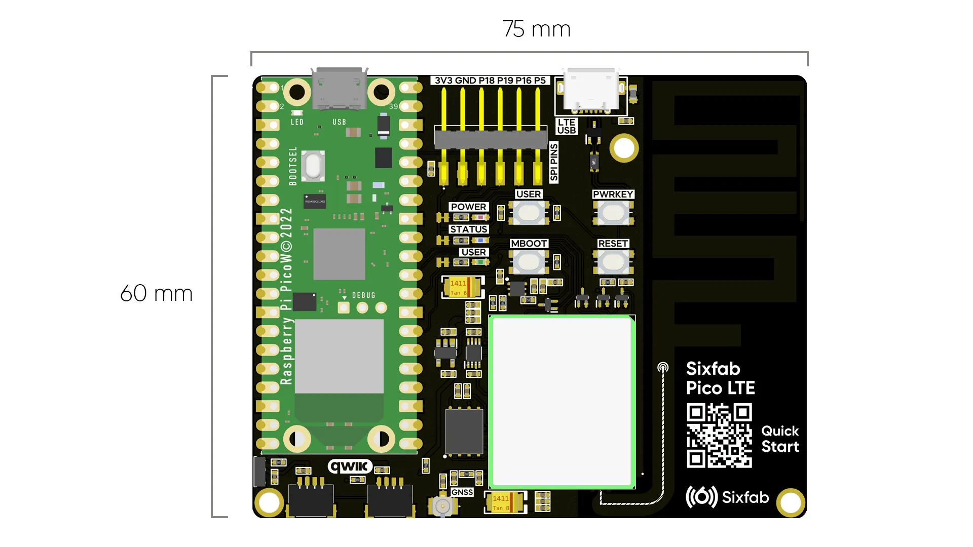
Dimension
Power
Rated input voltage(V): 5V DC
Rated input current(A): Max. 1.5A (When no sensor is connected)
The main power input for the Pico LTE board is the Micro USB connector located on the Pico W. It is designed to receive power only through these USB sockets and does not have any other power input ports.
LEDs
- USER LED: It is a programmable user-LED that can be controlled from the GP22 of Raspberry Pi for debugging or just fun.
- POWER LED: When power is supplied to the Pico LTE board through the micro USB input, the Power LED lights up.
- STATUS LED: It indicates the status of the LTE module. The following statuses are indicated based on the blinking pattern:
| Logic Level Changes | Network Status |
|---|---|
| Flicker slowly (200 ms High/1800 ms Low) | Network searching |
| Flicker slowly (1800 ms High/200 ms Low) | Idle |
| Flicker quickly (125 ms High/125 ms Low) | Data transfer is ongoing |
Buttons
- User Button: It is a programmable user button that is connected to GP21. It reads HIGH by default.
- PWRKEY Button: To power on/off the LTE module, press and release the button for 1 second.
- MBOOT Button: Force the module into emergency download mode.
- RESET Button: Reset Raspberry Pi Pico W when pressed.
GNSS
Pico LTE includes a fully integrated global navigation satellite system solution that supports GPS, GLONASS, BDS, Galileo and QZSS.
By default, LTE Module GNSS engine is switched off. It has to be switched on via AT command. The module does not support concurrent operation of WWAN and GNSS. For more details about GNSS engine technology and configurations, see this document.
The Pico LTE board is designed to work only with a passive GNSS antenna. Please use only a passive GNSS antenna and note that the kit does not include a GNSS antenna.
Region
Global (CAT-M Availability)
Environmental
Max. operating temp. -10°C to 50°C
Frequency Bands
B2 / B3 / B4 / B8 / B12 / B13 / B20
Protocols
TCP / UDP / SSL / TLS / FTP(S) / HTTP(S) / NITZ / PING / MQTT / LwM2M / CoAP
Data
The presented data rates(kbps) are theoretical only, and the actual value depends on network conditions.
Cat M1: Max. 588 kbps (DL) Max. 1119 kbps (UL)
LTE Module Specifications
The module used in Pico LTE kit is the Quectel BG95-M3 LTE Cat M1. For Quectel BG95-M3 specifications and more details, please check the specification file of the module. Please kindly note that certain features of the module may have limitations due to the customized antenna design and SIM configuration.
Antenna
Pico LTE has a built-in LTE Antenna design on the board to provide the best efficiency communication on the frequencies it supports. In this way, you do not need to search for and obtain a suitable antenna. You save both time and cost. Datasheet link for antenna details: Pico LTE Datasheet
- Terminal antenna for LTE-M applications.
- 4G bands: B2, B3, B4, B8, B12, B13, B20.
- 1850-1910MHz, 1710-1725MHz, 1710-1755MHz, 880-915MHz,699- 716MHz, 777-787MHz,832-862 MHz.
- High-performance mounted antenna design.
- Dimensions (20 mm X 60 mm).
- Available in two terminal options: Vertical and Horizontal allocations.
Compliance
Regulatory standards
Updated 8 months ago