Technical Details
This section introduces the concepts and terms that are crucial for the understanding, implementation and use of Sixfab 4G/LTE Cellular Modem Kit
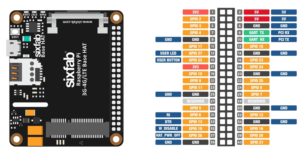
Pinout

Pin Descriptions
| Pin Number | BCM Pin | Pin Name | Description |
|---|---|---|---|
| 8 | UART_TX | PCI RX | This pin functions as the serial data input to the module for UART communication. Disconnected by default. |
| 10 | UART_RX | PCI TX | This pin functions as the serial data output from the module for UART communication. Disconnected by default. |
| 13 | GPIO27 | USER LED | Active HIGH, to switch on the USER LED, the pin's state should be HIGH. |
| 15 | GPIO22 | USER BUTTON | This pin normally pulled-down to ground. When the button is pressed, pin switches to LOW. |
| 31 | GPIO6 | RI | This pin is Ring indicator functions as the indication for receiving call or SMS, can be calibrated to HIGH or LOW using the AT commands. |
| 33 | GPIO13 | DTR | When the module is in sleep mode, DTR pin allows to wake the module up by pulling it to LOW. |
| 35 | GPIO19 | W_DISABLE | This pin is used to turn Airplane Mode on the module, by pulling it HIGH. |
| 37 | GPIO26 | HAT_PWR_OFF | Power regulator control. Normally pulled-down, when this pin drove to HIGH, Hat's power will cut off. |
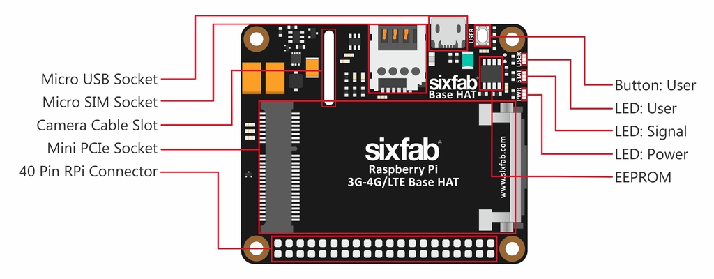
Layout

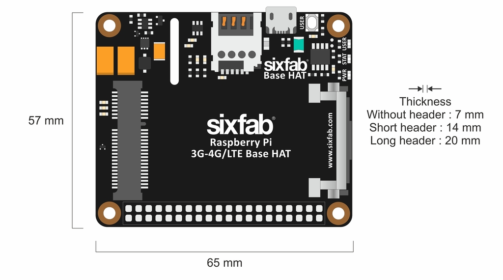
Dimension

LEDs
- PWR LED: When the module is powered up, this RED led turns on
- USER LED: It is a programmable user-led can be controlled from the GPIO27 of Raspberry Pi for debugging or just fun.
- SGNL LED: This BLUE led indicates the status of the connection. When the connection is established and data is being transmitted/received, this led will blink at special intervals. Otherwise, if there is no connection, the led will remain off.
📖 Note
With Telit Module attached to the Base HAT, the Status LED is off by default, It needs to be activated using the following AT commands.
AT#GPIO=1,0,2
AT#SLED=2
AT#SLEDSAV
The Status LED indicates the following states:
- Not registered: Always on
- Registered in idle: Blinking 1s on and 2s off
- Registered in idle with power-saving: Blinking time depends on network condition in order to minimize power consumption
Buttons
- User Button: It is a programmable user button that is connected to GPIO22. Reads HIGH by default.
Specifications

GNSS
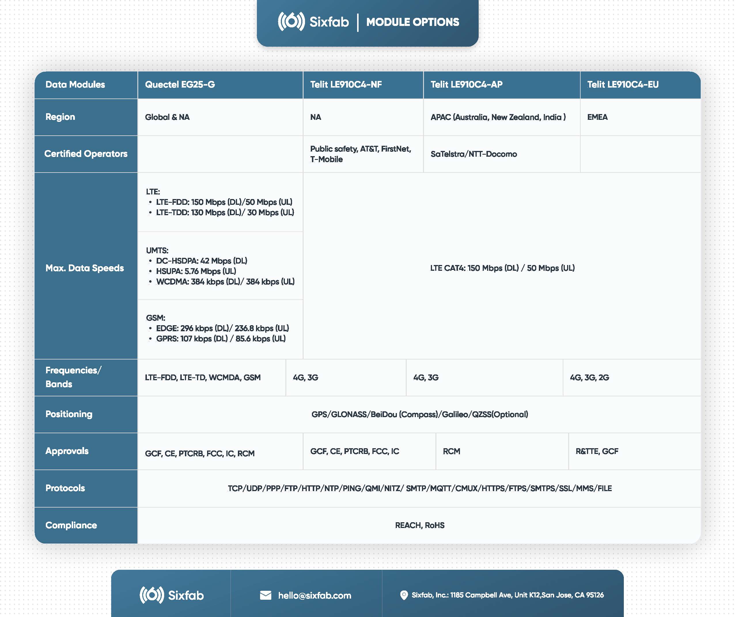
GPS, Glonass, Bei-dou, Galileo, QZSS
Environmental
Max. operating and storage temperature: -25°C to 70°C
Electrical
Rated input voltage(V): 5V DC
Rated input current(A): 3.0A
Compliance
- United States: FCC Part 15 Class B
- Canada: ICES-003 Class B
- Europe: CE, RoHS, Safety
Reports, and Other Resources
Updated 11 days ago
