Technical Specifications
Explore the technical details of the ALPON X5 AI on this page. Access comprehensive information about the device's hardware and electrical specifications.
Technical Specifications
Explore the technical details of the ALPON X5 AI on this page. Access comprehensive information about the device's hardware and electrical specifications.
Product Specifications
Mechanical & Environmental
| Dimensions | 100 x 100 x 45 mm (3.93 x 3.93 x 1.77 inch) without antennas |
| Weight | Approx. 457 grams (1 lb) |
| Case Material | Full aluminum enclosure, top side passively cooled |
| Protection Class * | IP40 |
| Operating Temperature | -20 °C to +60 °C (-4 °F to +140 °F) |
| Storage Temperature | -40 °C to +85 °C (-40 °F to +185 °F) |
| Max. Relative Humidity | Up to 95%, non-condensing |
| Environmental | Rugged, fanless design, suitable for industrial and harsh environments |
| Case Mounting Options | DIN Mount (Optional) Wall Mount (Optional) |
System
| AI Accelerator | DEEPX DX-M1 Ultra 2280 M.2 (25 TOPS) |
| Processor Generation | Raspberry Pi Compute Module 5 |
| Processor | Broadcom BCM2712 quad-core 64-bit Arm Cortex-A76 (Armv8) SoC @ 2.4GHz |
| Memory | 8GB, or 16GB LPDDR4-4267 SDRAM with ECC |
| Storage | Compute Module 5 eMMC (Optional) + NVMe SSD |
| Real Time Clock | CR1220 Coin Cell Battery |
Power
| Input Voltage & Power | DC Input: 9-30V DC, 27W USB PD: 15V DC 1.8A, 27W |
| Power Options | USB-PD Type-C Input Screw Terminal Block (9-30V DC) PoE+ IEEE 802.3at (Optional) |
| USB Output Voltage & Power | USB 3.0 5V DC, 1.8A (Total) |
Connectivity
| Wi-Fi | 2.4GHz and 5.0GHz IEEE 802.11 b/g/n/ac Wireless |
| Bluetooth | Bluetooth 5.0, BLE |
| Cellular Module * | 4G / LTE (Cat 4)* |
| Coverage | Global |
| Antennas | 2x Cellular (Main + Diversity) 1x GNSS 1x Wi-Fi |
| Outdoor IP67 Antenna (Optional) | 3-meter cabled combination antenna with surface mount |
| Positioning | GPS/GNSS, Cellular Geolocation |
| Data Speed ** | LTE-FDD (Mbps): Max. 150 (DL) / Max. 50 (UL) LTE-TDD (Mbps): Max. 130 (DL) / Max. 30 (UL) |
Input / Output
| USB | 2x USB 3.0, 1x USB Type-C OTG (boot/burn/power) |
| GPIO Port | 1x RJ45 (I2C, UART, SPI, 5V, GND) |
| Button | 2x User Programmable Push Button |
| Ethernet | 2x 1Gbps LAN Port (RJ45)* |
| LED Indicators | 1x Programmable RGB 1x Cellular Status 1x Connection Status 1x Power Status |
| Display | 1x HDMI 2.0 port (up to 4Kp60 supported) |
| Switch | 1x Boot/Burn (DIP Switch), 1x Watchdog Enable/Disable (DIP Switch) |
Software
| Pre-Installed OS | Raspberry Pi Compatible ALPON OS with DEEPX Runtime support |
| ALPON Edge Software Features | Fleet Management, Device Management, Built-in Security |
| Network Management | Multi-network support (Gigabit Ethernet, dual-band Wi-Fi, LTE Cat 4) with automatic failover |
Security
| TPM | Infineon Technologies SLB 9670VQ2.0 TPM 2.0 module |
| Hardware Watchdog | Monitors device operation and resets it in case of failure |
Expansion and Features
| SIM Type | eSIM (eUICC) – Consumer Profile Management, Remote Download & Switch |
| Supported Modules | Supports ALPON Edge Add-on modules, multiple hardware expansions via GPIO and USB ports |
Other
| Regulatory Certifications | CE, FCC, IC, UKCA, RoHS, WEEE, REACH, ICASA, RCM |
| Network & Carrier * | Verizon, AT&T, T-Mobile, PTCRB, GCF |
| Warranty | 2 Year Limited Warranty |
| Production Availability | January 2034 |
| Value-added Services | Hardware customization Branding, labelling Remote support Add-on module customization Software containerization support Consulting services |
* This product supports only 4G/LTE networks, with no fallback to 2G/3G, and its performance on non-4G/LTE networks is not guaranteed.
** The presented data rates are theoretical only, and the actual value depends on network conditions.
* Certifications in progress
* In some variants, the ETH/G port replaces the PoE port.
Power
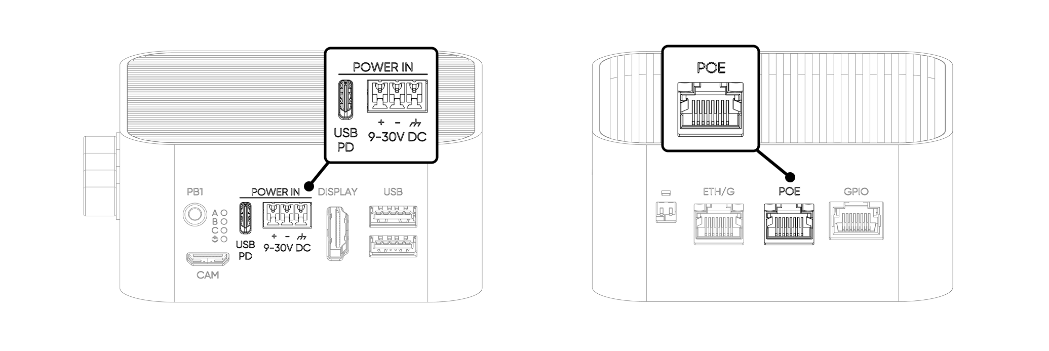
For powering the device, there are three available options: Type-C input, Screw Terminal Block, and Power over Ethernet (PoE). There is no priority among the power inputs. Power is consumed from the voltage with the highest capacity. The device must be operated with only one power input at a time. Connecting two or more power inputs at the same time is not recommended.
1. Type-C Input
From this port, the device is powered by a USB PD-enabled Type-C power adapter capable of providing 27W or more. We recommend using the power adapter included in the package.
| Parameter | Value |
|---|---|
| Recommended Adapter | 27W minimum at 15V; 45W adapter recommended for full performance |
| Supported Voltages | 12V / 2.25A (recommended: 12.0V / 3.75A) 15V / 1.8A (recommended: 15.0V / 3.0A) |
| USB-PD Mode | Sink only — no power output or USB data via this port |
| Exception | This port can be used as USB input in Burn (image flashing) mode only |
2. Screw Terminal Block
The terminal block is the recommended input for industrial deployments. It includes hardware-level reverse polarity protection to prevent damage from incorrect wiring. Pay attention to the polarity + / - connections.
| Parameter | Value |
|---|---|
| Input Voltage Range | 12V – 32V DC |
| Reverse Polarity Protection | Yes |
| Pin 1 | Chassis Ground |
| Pin 2 | Negative (–) |
| Pin 3 | Positive (+) |
3. Power over Ethernet (PoE)
Powering the device via PoE is only possible if the version includes a built-in PoE module, as the module cannot be added separately. The device supports the PoE+ (IEEE 802.3at) compliant. The power adapter must be PoE+ Class 4 (IEEE 802.3at) compliant. Other types of adapters are not supported and will not provide sufficient power for optimal device performance.
| Parameter | Value |
|---|---|
| Standard | IEEE 802.3at / PoE+ Class 4 |
| Input Voltage Range | 37V – 57V |
| Maximum Delivered Power | 25W |
| Supported Port | ETHERNET 0 only (PoE not available on ETHERNET 1) |
Restricted Mode
If the device is powered below 12V from any input source, it automatically enters Restricted Mode. This is a protective state designed to prevent hardware damage from undervoltage or insufficient current.
In Restricted Mode, only the following components remain powered:
- CM5 Compute Module
- LTE Modem
- ETHERNET 0
- ETHERNET 1
- USB Ports
- PCIe Interface (NVMe SSD and AI Accelerator)
- Add-on Port
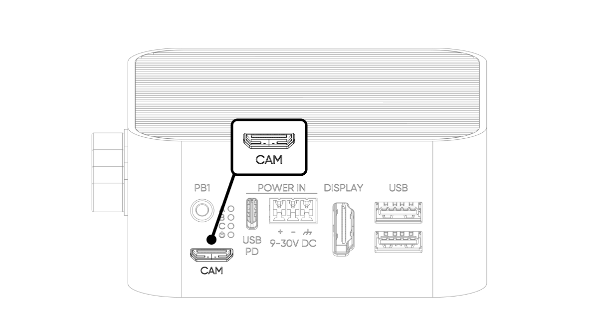
- Camera Port
Power Consumption
The table below shows measured power consumption values for each subsystem at three operating levels: idle, 50% load, and full load. Values marked with a dash (–) indicate that the subsystem draws negligible or no power at that load level independently.
| Component | Idle (W) | 50% Load (W) | Full Load (W) |
|---|---|---|---|
| CM5 | 4 | 7 | 10 |
| LTE Modem | 1 | 3 | 5 |
| Voltage Regulators | 1 | 2 | 3 |
| Add-on Port | – | – | 5 |
| USB 3.0 Ports | – | – | 9 |
| Camera Port | – | 1.4 | 2.5 |
| DEEPX AI Accelerator | 1 | 3 | 5 |
| NVMe SSD | 1 | 3 | 6 |
| TOTAL | 8 | 19.4 | 45.5 |
All values are approximate. Actual consumption may vary depending on workload, connected peripherals, and ambient temperature.
LEDs
The ALPON X5 AI has four LED indicators. They are connected to the system via an I2C I/O Expander (TCA6408, address 0x20) on the I2C1 bus (SDA: GPIO 2, SCL: GPIO 3).
One RGB LED is reserved for user applications. The remaining LEDs are controlled by ALPON cloud platform.
Below are all the details about LEDs.
| # | Label | Description |
|---|---|---|
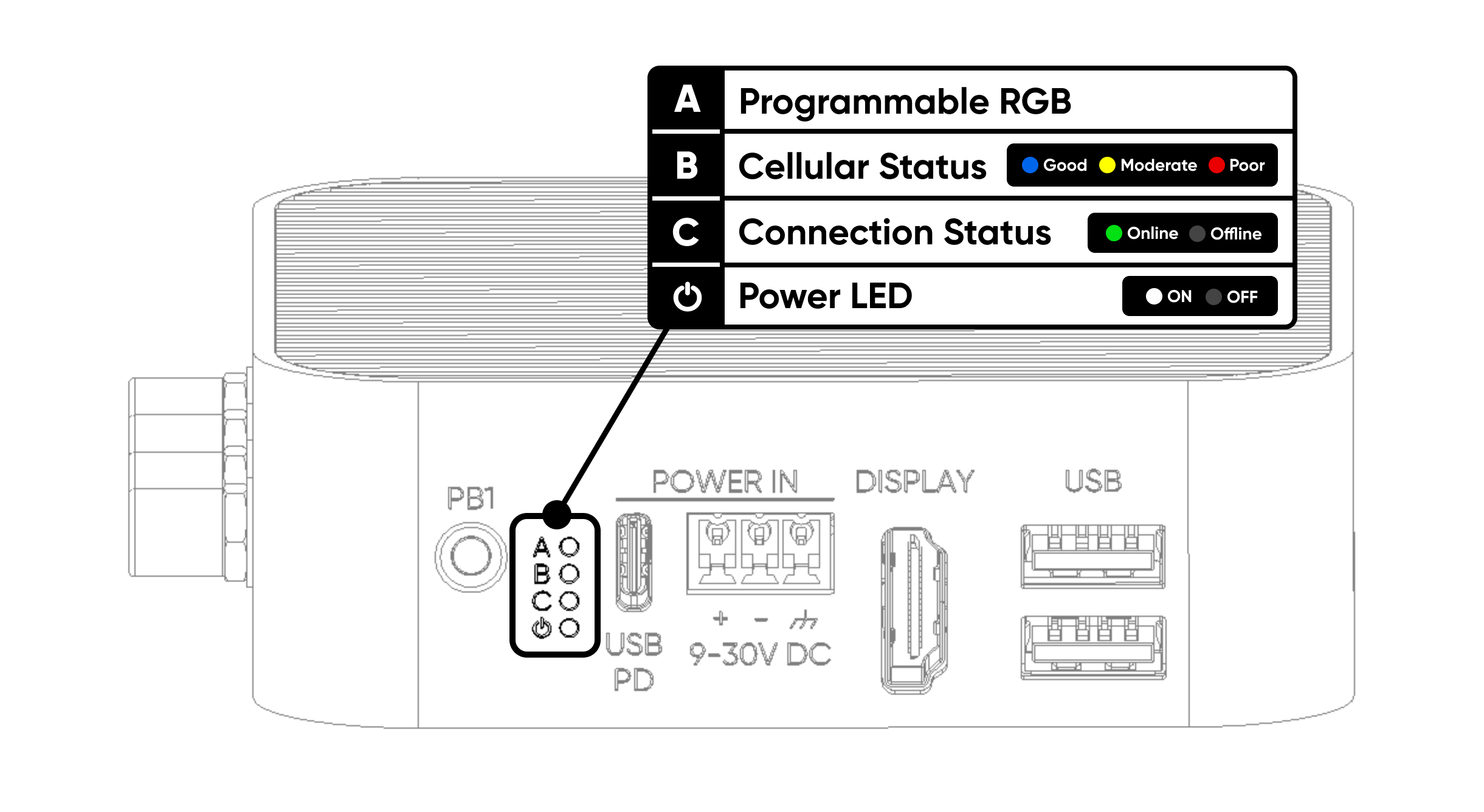
| A | Programmable RGB | Freely programmable via I²C (TCA6408A · 0x20). Pins: P2 Red · P3 Green · P4 Blue. |
| B | Cellular Status | Cellular connection quality. Red = poor · Yellow = moderate · Blue = good. |
| C | Connection Status | Device online status. Lights green when accessible via Sixfab Connect. |
| ⏻ | Power Status | Power LED. Turns white 3 seconds after the device powers on. |
Control RGB LED
The TCA6408A IC (Integrated Circuit) is used as the I/O expander and is connected to GPIO2 (SDA1) and GPIO3 (SCL1), i.e., I2C1 of the Compute Module 4. The I2C address of the TCA6408A is 0x20.
Here is the Python code and explanations to control LED A (Programmable RGB) connected.
🔗 GitHub GistView Python Script on GitHub GistThis Python script controls LED A on the ALPON X4 device. The LED is connected to three pins: P2 for Red, P3 for Green, and P4 for Blue. The script sets these pins as outputs and uses a function to change the LED's color by turning each pin on or off.
The script runs in a loop, showing red, green, blue, and then turning off the LED. It keeps repeating this cycle until the program is stopped, at which point the LED turns off.
Buttons
The device has two hardware buttons:
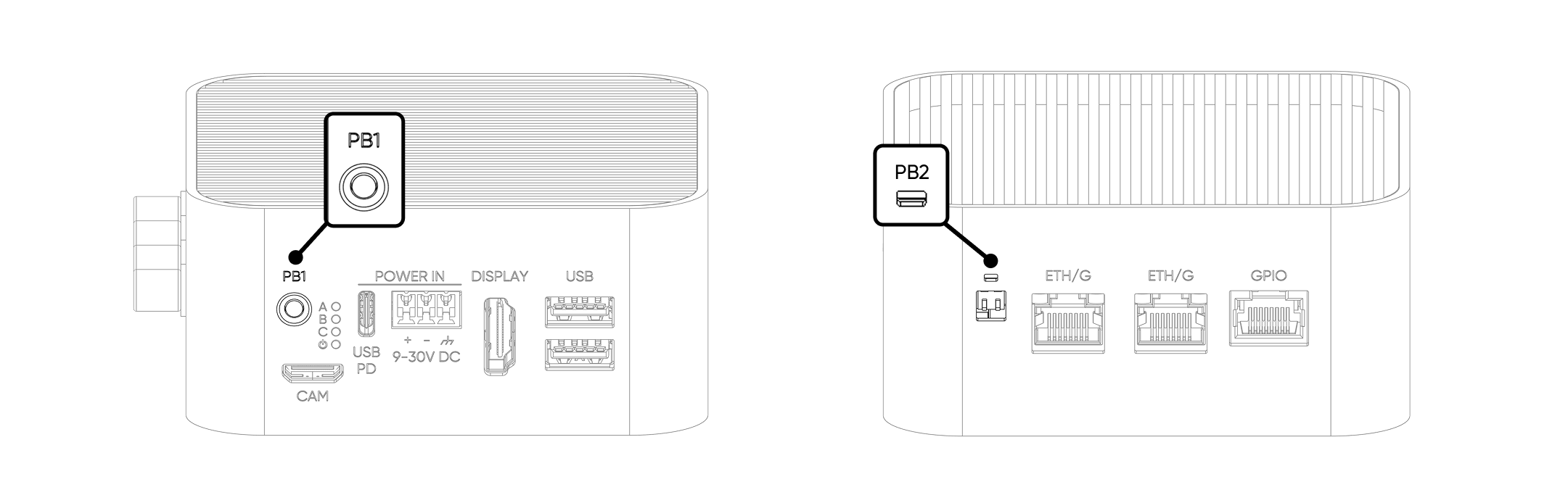
There are two user-configurable buttons that can be assigned to different functions:
| Button | Connected GPIO Pin |
|---|---|
| User Button (PB1) | GPIO5 |
| Reset Button (PB2) | GPIO6 |
By default, both buttons are in a HIGH state (PULL UP configuration). When pressed, the button is pulled LOW.
Display
Display capabilities are determined by the CM5 module. For the full list of supported modes, refer to the Raspberry Pi CM5 datasheet.
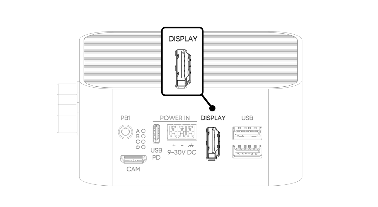
It can be connected to the monitor with a standard HDMI cable. HDMI should be connected before powering the ALPON X5. HDMI port supports 4Kp60 output.
| Parameter | Value |
|---|---|
| Port Standard | HDMI 2.0 |
| Maximum Resolution | 4K @ 60Hz (4Kp60) |
| HDR Support | Yes |
| Video Decoder | 4Kp60 HEVC (H.265) |
| Audio | Supported (HDMI audio pass-through) |
USB Ports
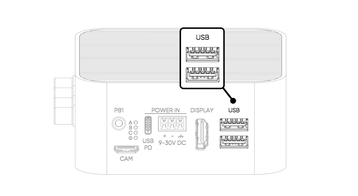
The device has two USB 3.0 ports (5 Gbps each).
| Parameter | Value |
|---|---|
| USB 3.0 Port 1 | Connected directly (native) to the CM5 |
| USB 3.0 Port 2 | Connected via TUSB8020 USB hub to CM5's second native port |
| Shared Power Capacity | 1800 mA total across both ports |
| Overcurrent Protection | Hardware current limiting; thermal shutdown if sustained overcurrent |
| Fault Reporting | Fault signal sent to TUSB8020 hub; OS-level alert generated in system logs |
| Power Recovery | Automatic — power restores when the fault is cleared, no reboot required |
Watchdog, Boot/Burn Switches
The switches on this product are covered with a silicone cap. To access the switches, use a pointed object to gently open from the notch on the cover.
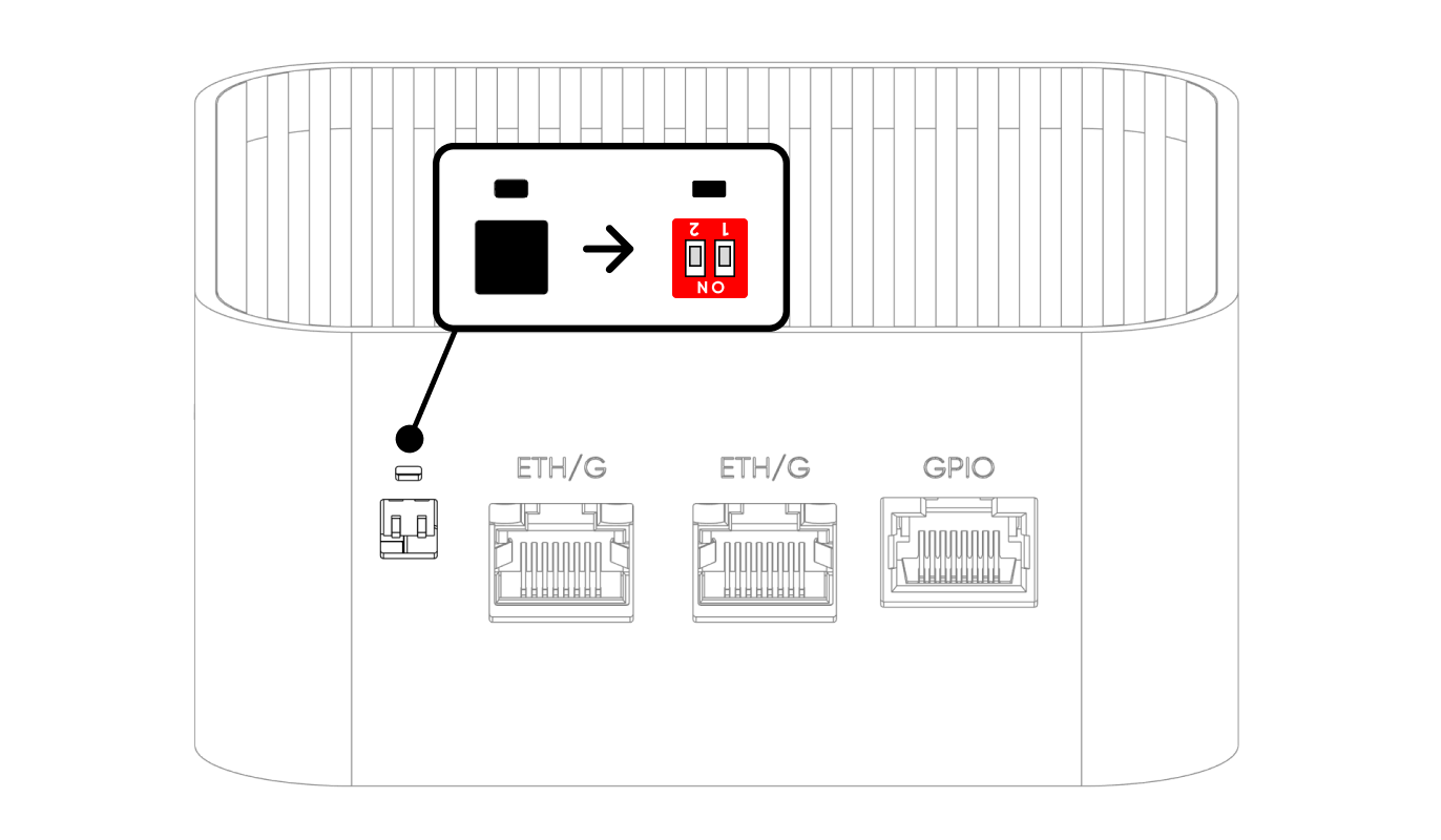
SW1 — Watchdog Switch
The hardware watchdog monitors system activity and automatically resets the device if it becomes unresponsive.
When the watchdog is enabled (SW1 OFF), the CM5 must send a periodic trigger signal to GPIO 16 at least once every 5 minutes. If no trigger is received within 5 minutes, the watchdog cuts all power to the device, waits 3 seconds, then restores power to reboot the system.
The watchdog can only be disabled using the physical SW1 switch. There is no software command to disable it.
SW2 — Boot / Burn (Image Flashing) Switch
| Position | Switch 1 | Switch 2 |
|---|---|---|
| ON | Watchdog Disabled | Burn (Image Flash Mode) |
| OFF (Default) | Watchdog Enabled | Boot (Operating Mode) |
Dimensions
Click here to download the ALPON X5 AI dimensions file.
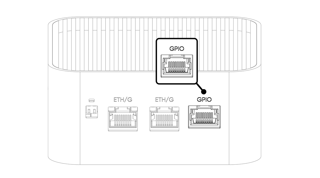
GPIO Port
This port provides the I/Os, supply voltage, and communication interfaces (I²C, UART, SPI) needed for various applications with the device. Although the socket is similar to the RJ45 socket, it is not for Ethernet communication. Instead, it provides access to Raspberry Pi's I/O pins for custom peripherals and Add-on modules.
Although the Add-on Port uses an RJ45 connector, it is NOT an Ethernet or PoE port. Connecting a standard Ethernet cable or PoE device to this port will cause permanent hardware damage. This port is exclusively for compatible ALPON Add-on modules.
| Connector Type | RJ45 (non-Ethernet — Add-on modules only) |
| GPIO Pins | 6 configurable GPIO pins (SPI5, UART4, UART0, I2C2, I2C3) |
| Signal Voltage | 3.3V logic (with built-in level converter and ESD protection) |
| Pull-up Resistors | 1 kΩ hardware pull-up on all signal pins |
| Power Output | 5V @ 1A maximum (5W) |
| Enable Pin | GPIO 21 — must be set HIGH before any I/O communication |
| Fault Detection | GPIO 20 — reads HIGH normally; goes LOW on overcurrent, overtemperature, or reverse voltage |
The port provides 6 configurable GPIO pins, a 5V power output, and a ground reference. All signal pins operate at 3.3V logic and include built-in level conversion and ESD protection. A 1 kΩ hardware pull-up resistor is present on every signal pin.
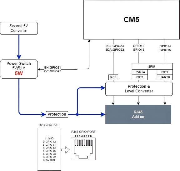
| RJ45 Pin | CM5 GPIO | Alternate Functions |
|---|---|---|
| 1 | GND | Ground |
| 2 | GPIO 12 | SPI5_CSn[0], UART4_TX, I2C2_SDA |
| 3 | GPIO 14 | SPI5_SIO[0], UART0_TX, I2C3_SDA |
| 4 | GPIO 13 | SPI5_SIO[1], UART4_RX, I2C2_SCL |
| 5 | GPIO 15 | SPI5_SCLK, UART0_RX, I2C3_SCL |
| 6 | GPIO 23 | I2C3_SCL |
| 7 | GPIO 22 | I2C3_SDA |
| 8 | 5V OUT | 5V power output, max. 1A — power-switch controlled (GPIO 21) |
Power Management & Fault Detection
The port's 5V supply and all signal communication are controlled by an internal power switch. The switch must be explicitly enabled in software before the port becomes active.
| Signal Name | CM5 GPIO | Description |
|---|---|---|
ADDON_PWS_EN | GPIO 21 | Power switch enable. Set HIGH to activate the port and enable I/O communication. Signal communication will not work until this pin is HIGH. |
ADDON_PWS_FAULT | GPIO 20 | Fault indicator. Reads HIGH during normal operation. Goes LOW if overcurrent, overtemperature, or reverse voltage is detected. Power to the port is cut automatically when a fault occurs. |
LTE Modem
| Parameter | Value |
|---|---|
| Host Interface | Native CM5 USB 2.0 |
| Power Circuit | 3.3V @ 3A |
| Typical Power Consumption | Up to 5W under active use |
| Default State | Powered ON at device startup (always active) |
| Hard Reset GPIO | GPIO 18 |
Performing a Modem Hard Reset
If the modem becomes unresponsive or loses its network connection, perform a hardware reset as follows:
- Set GPIO 18 to HIGH to cut power to the modem.
- Wait at least 10 seconds to allow internal capacitors to fully discharge.
- Set GPIO 18 back to LOW to restore modem power.
NPU & SSD Communication (PCIe)
Both the NVMe SSD and the DEEPX AI Accelerator communicate with the CM5 over PCIe Gen 3. The CM5's PCIe lane is split between the two devices using an ASM2806I PCIe Packet Switch, which ensures both the SSD and NPU share the high-speed PCIe bus efficiently.