
Technical Details
This section introduces the concepts and terms that are crucial for the understanding, implementation and use of Sixfab 5G Modem Kit
5G Modem Carrier HAT
The detailed specifications of the Raspberry Pi 5G HAT v2 are provided below.
Pinout
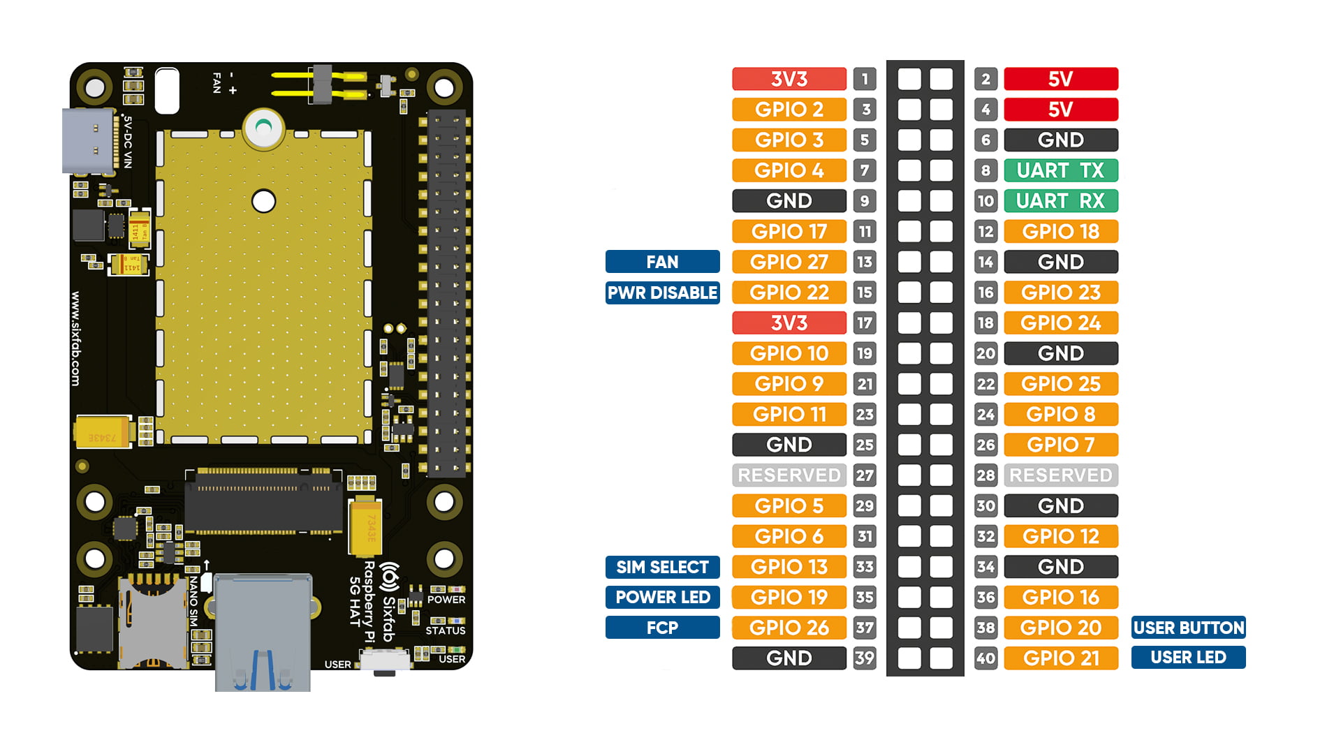
Pin Descriptions
| Pin Number | BCM Pin | Pin Name | Description |
|---|---|---|---|
| 33 | GPIO13 | SIM Select | Toggles between the physical SIM card and the onboard eSIM. • LOW (Default): Selects physical SIM card. • HIGH: Selects onboard eSIM. Note: Switching requires a module reboot. |
| 13 | GPIO27 | Fan On/Off - PWM Control | Controls active cooling fan. • HIGH: Turns fan ON (supports PWM speed control). • LOW (Default): Turns fan OFF. |
| 37 | GPIO26 | 5G Module FCP | Controls modem power-on/off sequences. • HIGH: Initiates module shutdown (powers off after 10 seconds). • LOW (Default): Initiates power-on sequence (fully operational after 50 seconds). |
| 40 | GPIO21 | User LED | Programmable status LED. • HIGH: Turns LED ON. • LOW: Turns LED OFF. |
| 38 | GPIO20 | User Button | Programmable input button. • HIGH (Default): Unpressed state. • LOW: Active state (when button is pressed). |
| 35 | GPIO19 | Power LED Off | Active-HIGH control to disable the onboard Power LED. • LOW (Default): Power LED remains illuminated. • HIGH: Power LED turns OFF. |
| 15 | GPIO22 | Power Disable | Hardware power cut-off for power cycling or power saving. • HIGH: Cuts off main power supply to the HAT (use for resetting unresponsive modules). • LOW (Default): Normal power delivery to the HAT. |
Layout
LEDs
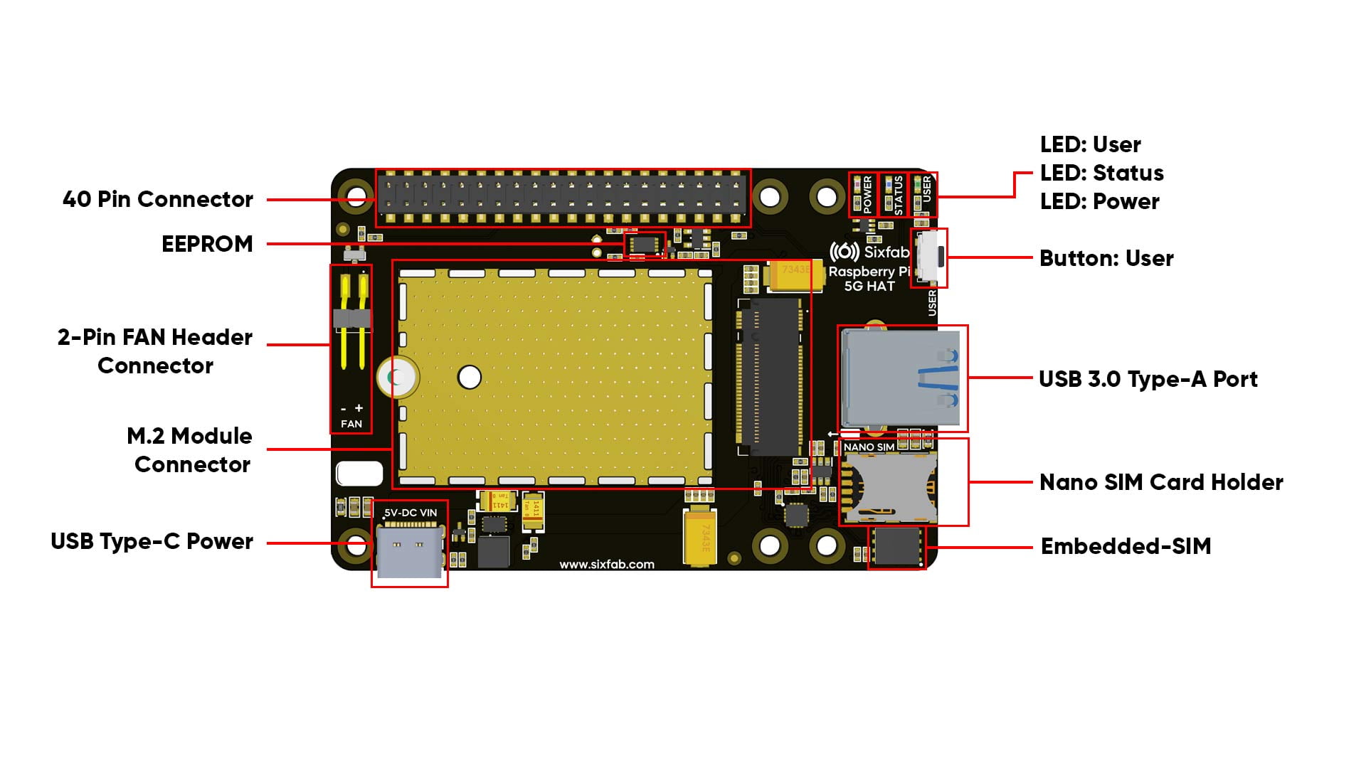
- POWER LED: Indicates power status of the HAT. Can be disabled by pulling GPIO19 HIGH.
- STATUS LED: Indicates the RF function of the module. Driven directly by Pin 10 (WWAN_LED#) of the M.2 connector. Its behavior depends entirely on how the M.2 module manufacturer (OEM) implements WWAN_LED# signal functionality.
- USER LED: A user-programmable LED connected to GPIO21 for custom debugging or status indications.
Buttons
- User Button: A user-programmable push button connected to GPIO20 (pulled HIGH by default)
Compatible M.2 Modules
The Sixfab 5G Development Kit v2 supports a wide range of M.2 5G cellular modules.
The modules listed below have been pre-tested and validated by Sixfab for full hardware and software compatibility.
The modules listed below have been tested and confirmed compatible for standard cellular operations with the kit.
| Manufacturer | Tested Module Series |
|---|---|
| Quectel | RM50xQ, RM5x0N, EM05, EM06 |
NotesThe HAT routes primary power, high-speed USB data lines, control signals, and default SIM interfaces. Certain secondary or specialized module pins (such as PCM/I2S audio or additional hardware-specific interfaces) are not routed through the board.
Verifying Third-Party M.2 Pinout Compatibility
If you plan to use an M.2 5G module that is not listed in the pre-tested table, you must independently verify its pinout compatibility before inserting it into the HAT. While M.2 is an industry standard, power pins, USB interfaces, and control signals can vary across manufacturers.
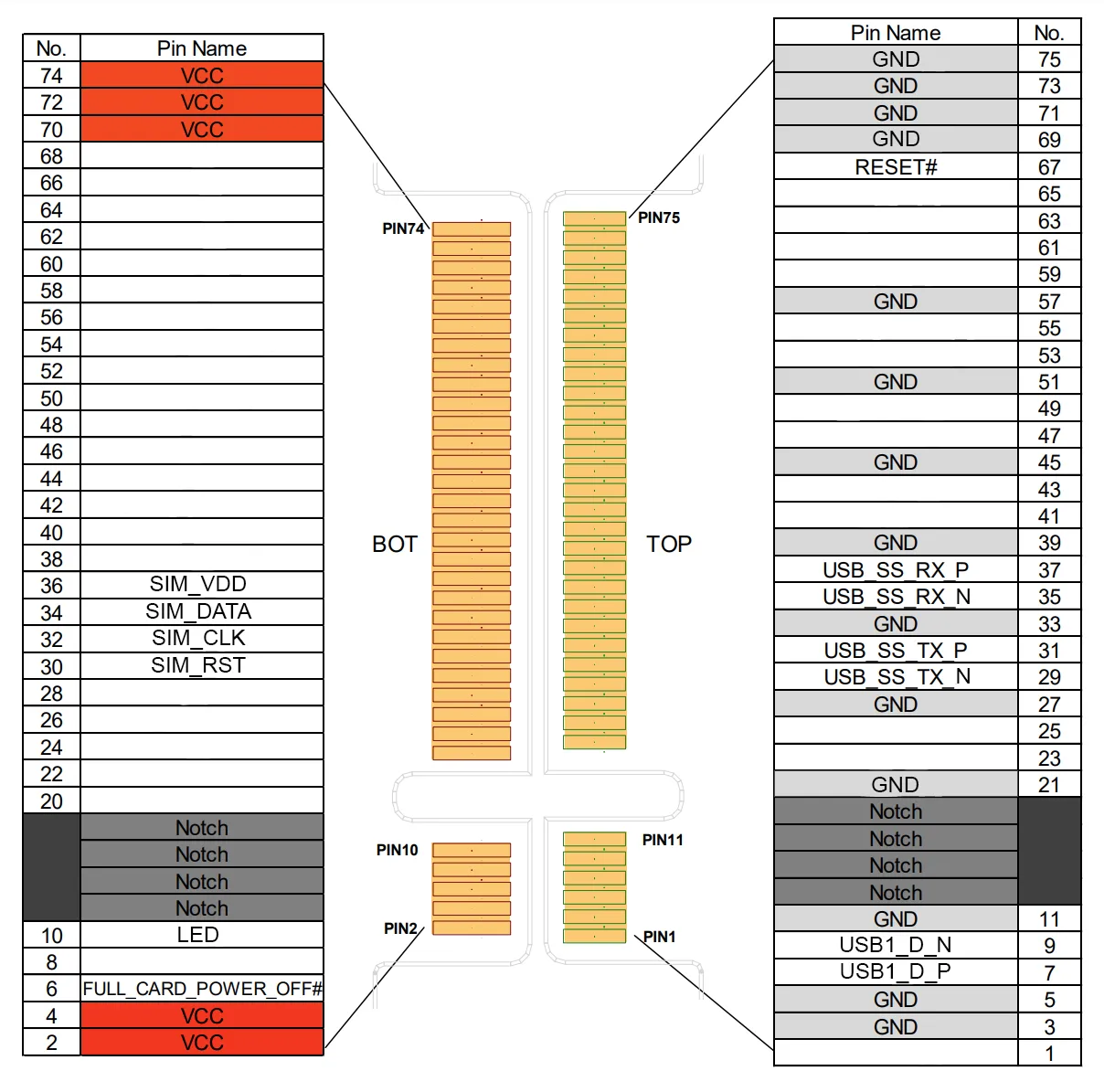
Compare your module's hardware specification manual against the Sixfab M.2 5G HAT v2 Pinout Assignment diagram below.
Key Pins to Cross-Check
When reviewing your module’s datasheet, verify that the following essential signal groups match the HAT's pinout:
- Power & Ground (VCC / GND): Ensure input voltage pins and ground lines line up and verify that your module can tolerate the HAT's 4.2V power rail.
- USB Data Lines (USB 3.0 & USB 2.0): Confirm that SuperSpeed TX/RX and USB 2.0 D+/D- lines match the host bridge routing.
- SIM Interfaces: Verify that SIM control, data, clock, and reset pins map correctly to support the SIM.
Updated about 22 hours ago