Technical Details
Explore the technical details of the ALPON X4 on this page. Access comprehensive information about the device's hardware and electrical specifications.
Technical Details
Explore the technical details of the ALPON X4 on this page. Access comprehensive information about the device's hardware and electrical specifications.
Product Specifications
1. Mechanical & Environmental
| Dimensions | 111.16 x 99.9 x 33 mm (4.37 x 3.93 x 1.30 inch) without antennas |
| Weight | Approx. 457 grams (1 lb) |
| Case Material | Full aluminum enclosure, top side passively cooled |
| Protection Class * | IP40 |
| Operating Temperature | -20 °C to +60 °C (-4 °F to +140 °F) |
| Storage Temperature | -40 °C to +85 °C (-40 °F to +185 °F) |
| Max. Relative Humidity | Up to 95%, non-condensing |
| Environmental | Rugged, fanless design, suitable for industrial and harsh environments |
| Case Mounting Options | DIN Mount (Optional) · Wall Mount (Optional) |
2. System
| Processor Generation | Raspberry Pi Compute Module 4 |
| Processor | Broadcom BCM2711 Cortex-A72 (ARM v8) Quad-core ARM Cortex-A72 @ 1.5GHz |
| Memory | 8GB LPDDR4 (optional: 2GB, 4GB) |
| Storage | 32GB eMMC Flash storage (optional: 8GB, 16GB) |
| Real Time Clock | CR1220 Coin Cell Battery |
3. Power
| Input Voltage & Power | DC Input: 9–30V DC, 27W · USB PD: 15V DC 1.8A, 27W |
| Power Options | USB-PD Type-C Input · Screw Terminal Block (9–30V DC) · PoE+ IEEE 802.3at (Optional) |
| USB Output Voltage & Power | USB 2.0 5V DC, 1A (Total) |
4. Connectivity
| Wi-Fi | 2.4GHz and 5.0GHz IEEE 802.11 b/g/n/ac Wireless |
| Bluetooth | Bluetooth 5.0, BLE |
| Cellular Module * | 4G / LTE (Cat 4) |
| Coverage | Global |
| Antennas | 2x Cellular (Main + Diversity) · 1x GNSS · 1x Wi-Fi |
| Outdoor IP67 Antenna (Optional) | 3-meter cabled combination antenna with surface mount |
| Positioning | GPS/GNSS, Cellular Geolocation |
| Data Speed ** | LTE-FDD: Max. 150 Mbps (DL) / Max. 50 Mbps (UL) · LTE-TDD: Max. 130 Mbps (DL) / Max. 30 Mbps (UL) |
5. Input / Output
| USB | 2x USB 2.0 High-Speed Stack Port |
| GPIO Port | Access to 6x RPi GPIO Pins, GND, 5V DC Output (1A max.) |
| Button | 2x User Programmable Push Button |
| Ethernet | 1x 100 Mbps LAN Port · 1x 1 Gbps LAN Port * |
| LED Indicators | 1x Programmable RGB · 1x Cellular Status · 1x Connection Status · 1x Power Status |
| Display | 1x HDMI 2.0 port (up to 4Kp30 supported) |
| Switch | 1x Boot/Burn · 1x Watchdog |
6. Software
| Pre-Installed OS | Pre-installed Official Raspberry Pi OS with ALPON Edge Software; visual platform and API-driven interaction with ALPON Cloud |
| ALPON Edge Software Features | Fleet Management, Device Management, Built-in Security |
| Network Management | Multi-network support (Gigabit Ethernet, dual-band Wi-Fi, LTE Cat 4) with automatic failover |
7. Security
| TPM | Infineon Technologies SLB 9670VQ2.0 TPM 2.0 module |
| Hardware Watchdog | Monitors device operation and resets it in case of failure |
8. Expansion and Features
| SIM Type | eSIM (eUICC) – Consumer Profile Management, Remote Download & Switch |
| Supported Modules | Supports ALPON Edge Add-on modules, multiple hardware expansions via GPIO and USB ports |
9. Other
| Regulatory Certifications | CE, FCC, IC, UKCA, ICASA *, RCM *, RoHS, WEEE, REACH |
| Network & Carrier * | Verizon, AT&T, T-Mobile, PTCRB, GCF |
| Warranty | 2 Year Limited Warranty |
| Production Availability | January 2034 |
| Value-added Services | Hardware customization · Branding & labelling · Remote support · Add-on module customization · Software containerization support · Consulting services |
* This product supports only 4G/LTE networks, with no fallback to 2G/3G, and its performance on non-4G/LTE networks is not guaranteed.
** The presented data rates are theoretical only, and the actual value depends on network conditions.
* Certifications in progress.
* In some variants, the ETH/G port replaces the PoE port.
1. Power
For powering the device, there are three available options: Type-C input, Screw Terminal Block, and Power over Ethernet (PoE). There is no priority among the power inputs. Power is consumed from the voltage with the highest capacity. The device must be operated with only one power input at a time. Connecting two or more power inputs at the same time is not recommended.
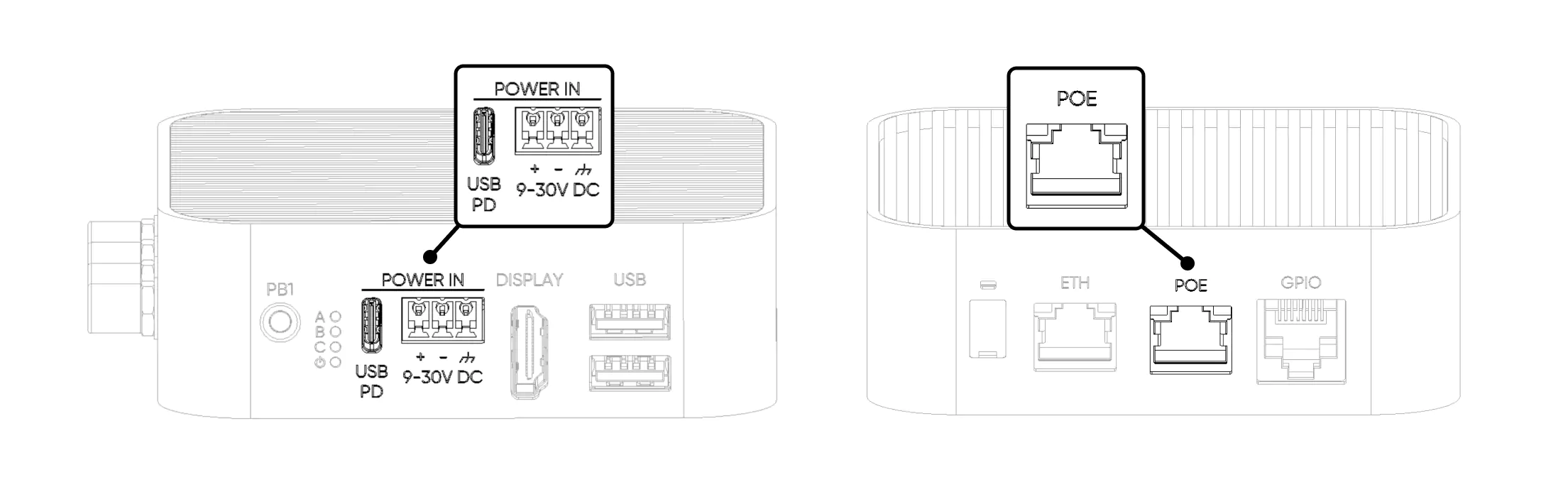
1. Type-C Input
From this port, the device is powered by a USB PD-enabled Type-C power adapter capable of providing 27W or more. We recommend using the power adapter included in the package.
2. Screw Terminal Block
It is used to power the device with an external power adapter. A minimum of 30W with either 12V or 24V DC adapter or another power source can be used. Pay attention to the polarity + / – connections.
3. Power over Ethernet (PoE)
Powering the device via PoE is only possible if the version includes a built-in PoE module, as the module cannot be added separately. The device supports the PoE+ (IEEE 802.3at) standard. The power adapter must be PoE+ Class 4 (IEEE 802.3at) compliant. Other types of adapters are not supported and will not provide sufficient power for optimal device performance.
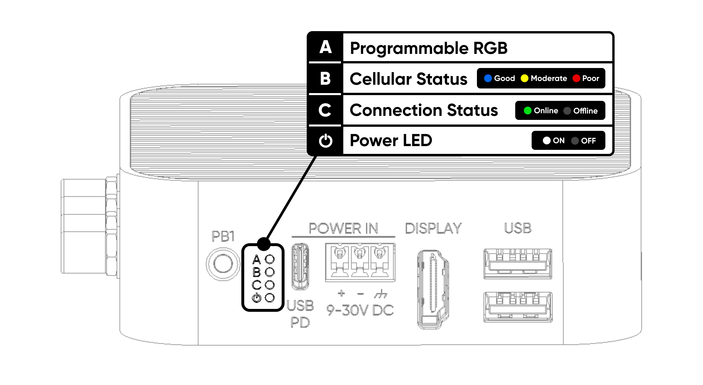
2. LEDs
The ALPON X4 has four LED indicators. One RGB LED is reserved for user applications. The remaining LEDs are controlled by the ALPON cloud platform.
| # | Label | Description |
|---|---|---|
| A | Programmable RGB | Freely programmable via GPIO. |
| B | Cellular Status | Shows the cellular connection status and quality. Red indicates poor, yellow indicates moderate, and blue indicates a good connection. |
| C | Connection Status | Indicates whether the device is online. If accessible via Sixfab Connect, it lights up green. |
| ⏻ | Power Status | This is the power LED. It turns white 3 seconds after switching on the device. |
Control RGB LED
The TCA6408A IC is used as the I/O expander and is connected to GPIO2 (SDA1) and GPIO3 (SCL1) — i.e., I2C1 of the Compute Module 4. The I2C address of the TCA6408A is 0x20.
The LED A (Programmable RGB) is connected to three pins: P2 for Red, P3 for Green, and P4 for Blue.
🔗 GitHub GistView RGB LED Python Script on GitHubThe script sets the LED pins as outputs and cycles through red, green, blue, then off — repeating until stopped.
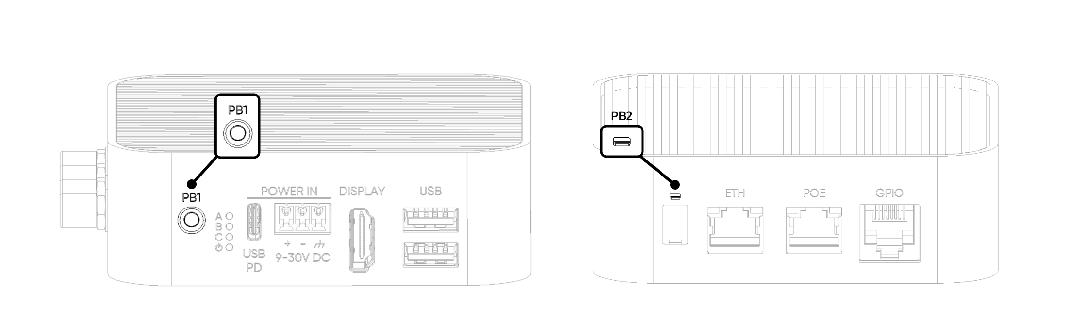
3. Buttons
The device has two user-configurable hardware buttons that can be assigned to different functions.
| Button | Connected GPIO Pin |
|---|---|
| User Button (PB1) | GPIO5 |
| Reset Button (PB2) | GPIO6 |
By default, both buttons are in a HIGH state (PULL UP configuration). When pressed, the button is pulled LOW.
4. Display
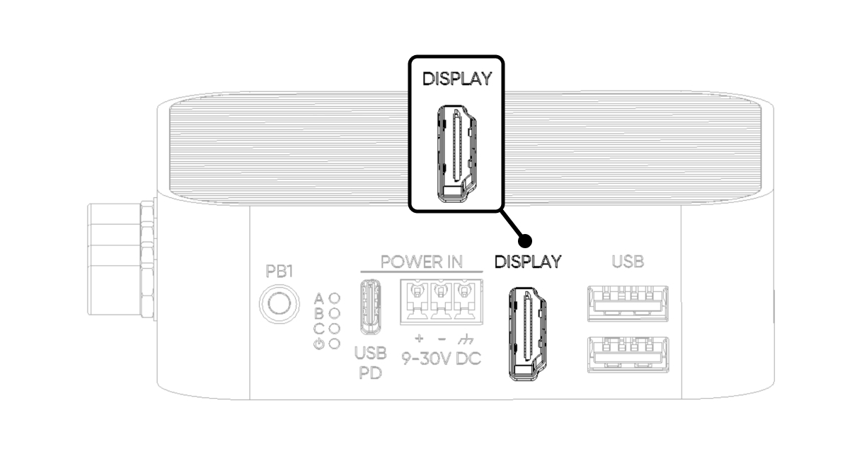
It can be connected to a monitor with a standard HDMI cable. HDMI should be connected before powering the ALPON X4. The HDMI port supports 4K 30fps output.
| Parameter | Value |
|---|---|
| Port Standard | HDMI 2.0 |
| Maximum Resolution | 4K @ 30Hz (4Kp30) |
5. USB Ports
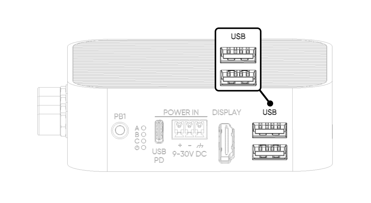
The device has 2x USB 2.0 ports. By default, when connected to these ports, devices will be recognized as directly connected to the Raspberry Pi CM4 USB port.
The combined current output capacity for both ports is 1A. You can connect a single device drawing up to 1A, or two devices with a combined draw of no more than 1A across both ports. If this limit is exceeded, power to both ports will be cut off. To restore power, the device needs to be completely shut down and powered on again.
6. Watchdog & Boot/Burn Switches
The switches on this product are covered with a silicone cap. To access the switches, use a pointed object to gently open from the notch on the cover.
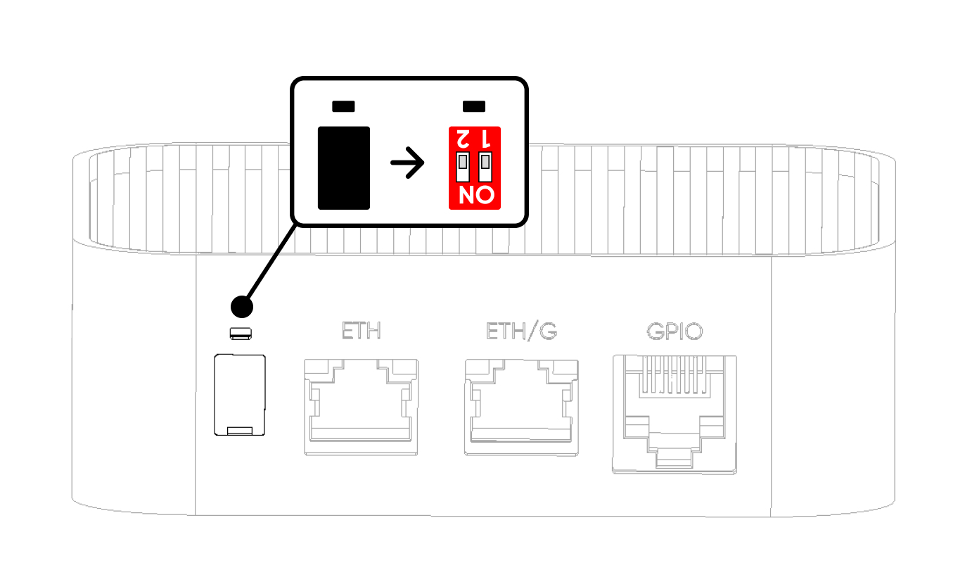
| Position | Switch 1 — Watchdog | Switch 2 — Boot/Burn |
|---|---|---|
| ON | Watchdog Inactive | Burn (Image Flash Mode) |
| OFF (Default) | Watchdog Active | Boot (Operating Mode) |
7. Dimensions
Click here to download the ALPON X4 dimensions file.
8. GPIO Port
This port provides the I/Os, supply voltage, and communication interfaces (I²C, UART, SPI) needed for various applications with the device. Although the socket is similar to the RJ45 socket, it is not for Ethernet communication. Instead, it provides access to Raspberry Pi's I/O pins for custom extensions.
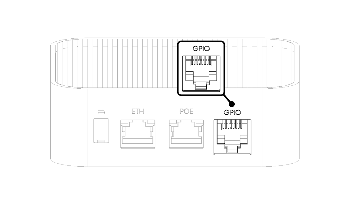
The pins are not directly connected to the connector. To ensure greater stability for long connections, they are routed through a voltage-level converter before exiting the RJ45 socket.
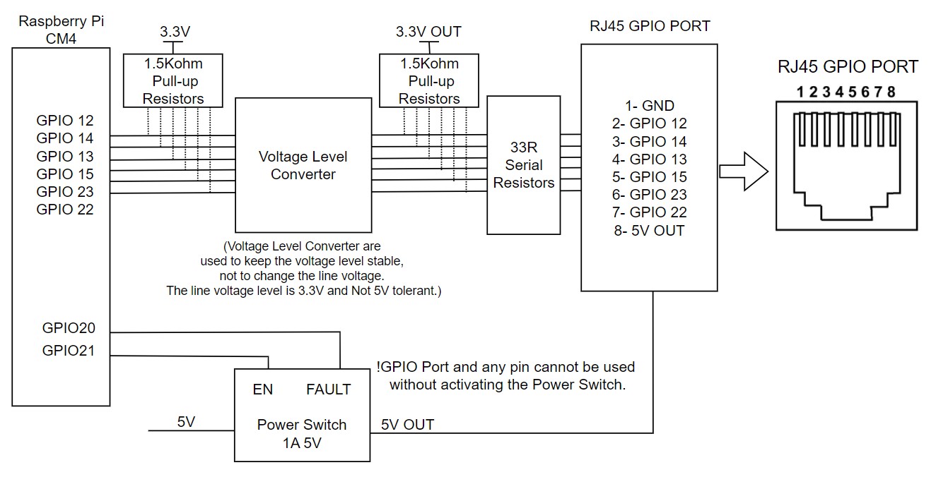
When powering on the ALPON X4, the 5V pin on the I/O port is initially off. To activate the I/O power and signal communication, GPIO 21 must be set to logic HIGH (1). If there is a short circuit or overcurrent on the I/O power line, the port enters protection mode. GPIO 20 will remain LOW while the fault persists, then return HIGH once resolved.
| RJ45 Pin | CM4 GPIO | Alternate Functions |
|---|---|---|
| 1 | GND | Ground |
| 2 | GPIO 12 | SPI5_CSn[0], UART4_TX, I2C2_SDA |
| 3 | GPIO 14 | SPI5_SIO[0], UART0_TX, I2C3_SDA |
| 4 | GPIO 13 | SPI5_SIO[1], UART4_RX, I2C2_SCL |
| 5 | GPIO 15 | SPI5_SCLK, UART0_RX, I2C3_SCL |
| 6 | GPIO 23 | I2C3_SCL |
| 7 | GPIO 22 | I2C3_SDA |
| 8 | 5V OUT | 5V power output, max. 1A — power-switch controlled via GPIO 21 |
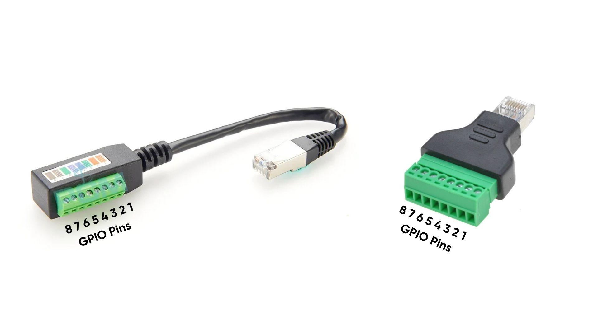
When RJ45-to-terminal block adapters are attached, the GPIO port pins are configured as shown in the diagram below.
Integration and Programming
Configuring SPI
For SPI communication, utilize the SPI pins (GPIO12, GPIO14, GPIO13, GPIO15):
import spidev

spi = spidev.SpiDev()
spi.open(0, 0)          # Open SPI bus 0, device (CS) 0
spi.max_speed_hz = 50000  # Set SPI speed
spi.xfer2([0x01, 0x02]) # Example transfer
Configuring I²C
Use the I²C pins (GPIO23 and GPIO22) for I²C communication:
import smbus

bus = smbus.SMBus(1)          # Open I2C bus 1
address = 0x20               # I2C address of the device
bus.write_byte(address, 0x01) # Example write
data = bus.read_byte(address) # Example read