Technical Details
This section introduces the concepts and terms that are crucial for the understanding, implementation and use of Sixfab Power Management & UPS HAT v2.
Hardware Details
Hardware specifications
- Microchip ATSAMD21G18 ARM® Cortex®-M0+ Microcontroller
- Texas Instruments bq25703A Multi-Chemistry Battery Buck-Boost Charge Controller With System Power Monitor and Processor Hot Monitor
- Texas Instruments bq27441-G1 System-Side Impedance Track™ Fuel Gauge
- Texas Instruments INA219 Zerø-Drift, Bidirectional Current/Power Monitor
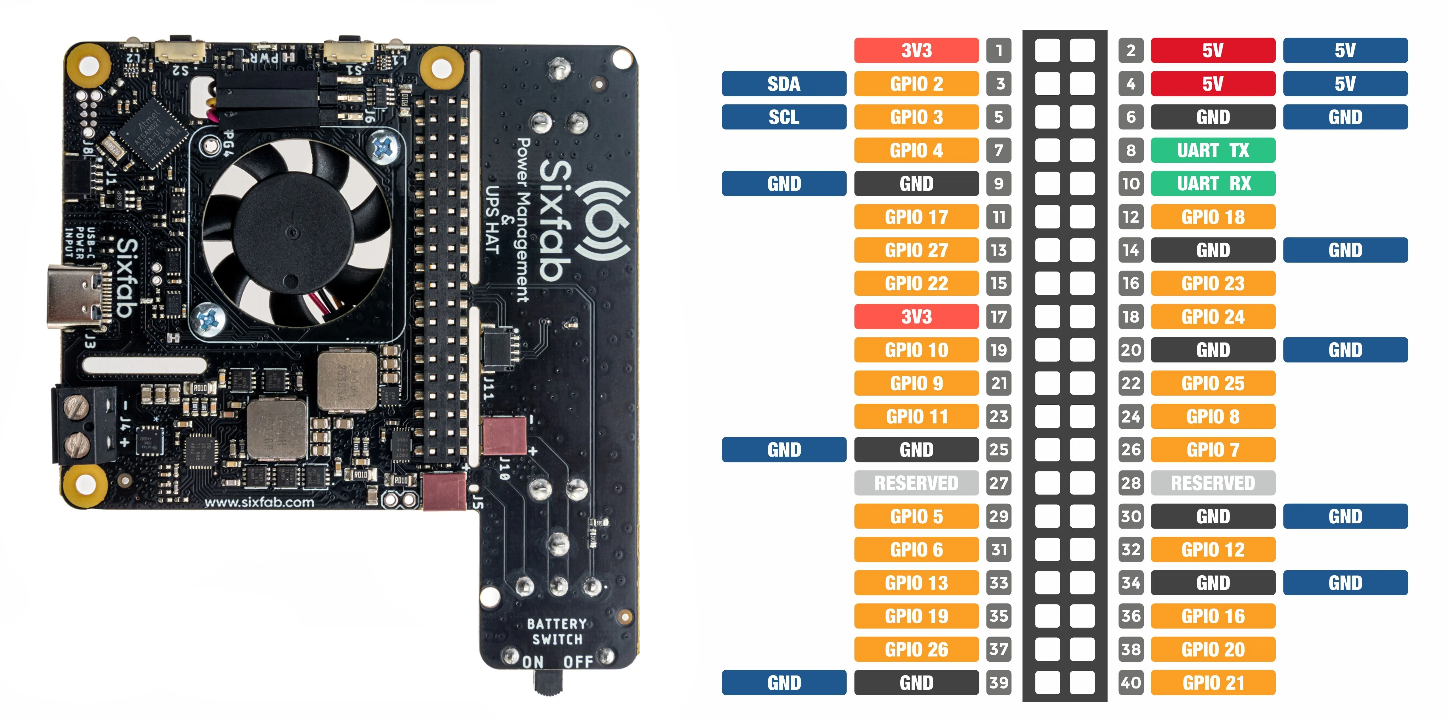
Pinout

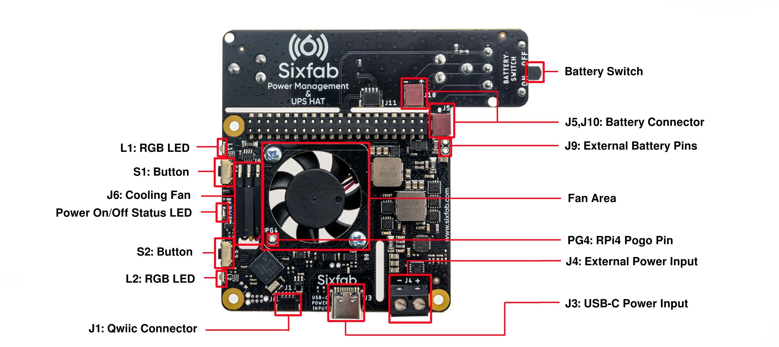
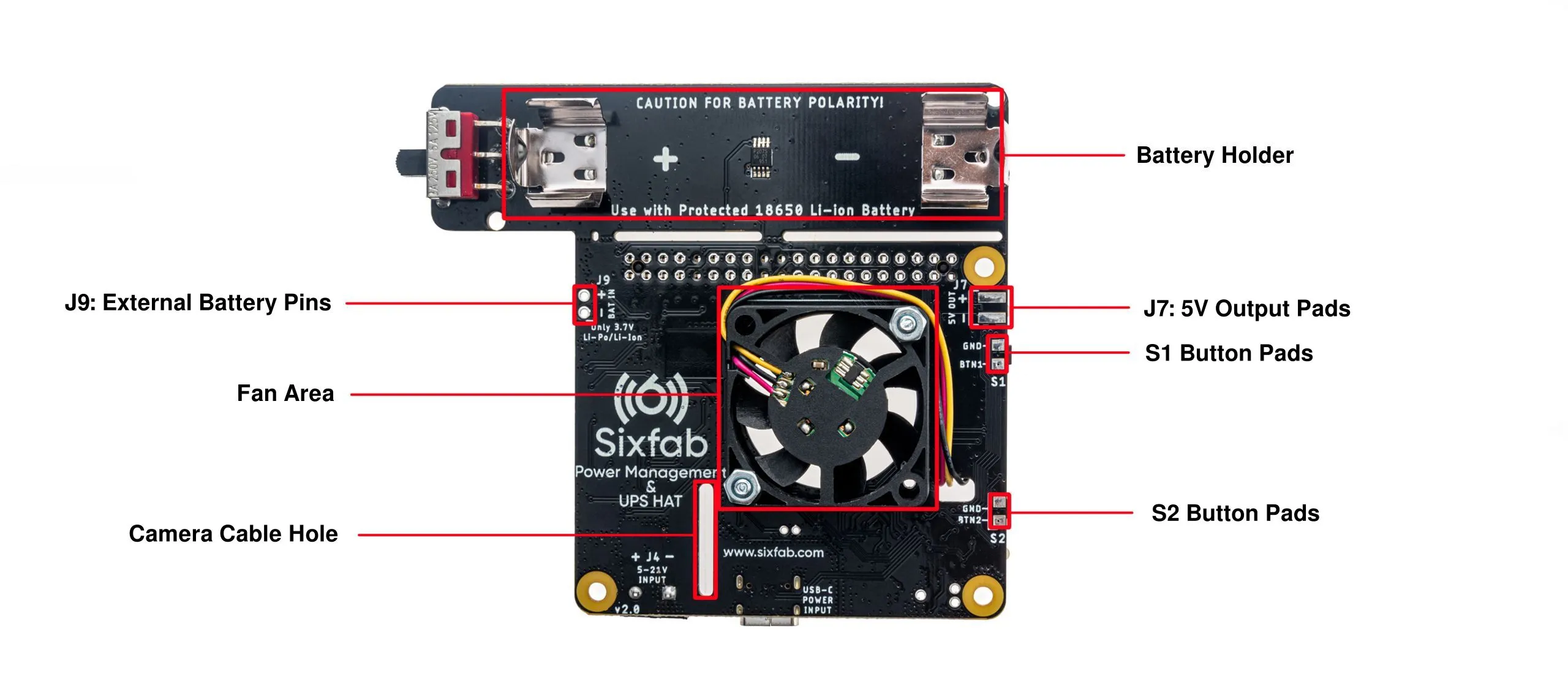
Layout


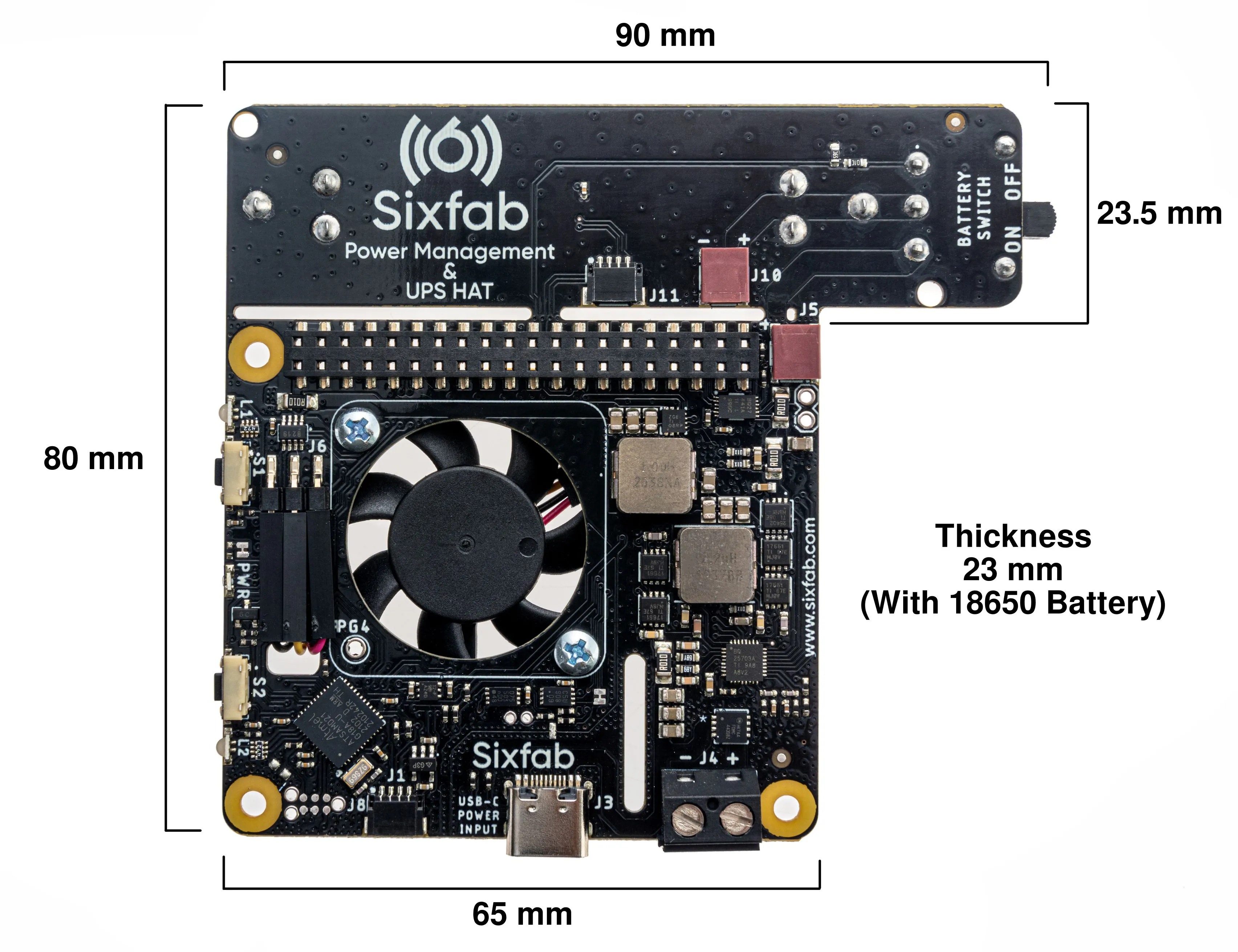
Dimension

Power Inputs/Outputs
| Inputs/Outputs | Description |
|---|---|
| J3 | USB Type-C 5V 3A max. input |
| J4 | Terminal Block 5V to 21V. 4A max. current input. |
| J7 | 5V rated 2.6A max output, solderable pads on the bottom side. |
🔍 Info
- The recommended input voltage is 5V and the input current is 2A minimum. For the 12V input voltage, the minimum is 1.5A. We recommend the official Raspberry Pi power supply.
- An external device can be connected to J7 for 5V output(underneath the HAT) and be aware of the polarity when sourcing via J7.
📖 Note
- Use only one of these two inputs(J3, J4) at a time, i.e. do not plug a USB(J3) adapter while a power source is inserted through the terminal block(J4) or the other way.
- The UPS HAT has several Battery input options such as J5, J9. Do not use multiple batteries at a time.
Battery(Not Included)
The HAT comes with an integrated Protected 18650 Li-on battery holder without a battery.
You can plug an external single-cell 3.7V Li-on or Li-po rechargeable batteries when bigger capacities or special dimensions are needed at J5(using Battery Cable JST-SFH) or J9 connector.
Battery Discharge Time
For 3500 mAh Battery
| Device / Task | Idling | With Base HAT 4G Connection - Idle | With Cellular IoT HAT Cellular Connection - Idle |
|---|---|---|---|
| Raspberry Pi 4 (2 GB) | 5 Hrs 36 Min | 4 Hrs 35 Min | 4 Hrs 45 Min |
| Raspberry Pi 3B+ (1 GB) | 5 Hrs 58 Min | 5 Hrs 3 Min | 5 Hrs 29 Min |
Buttons
There are two right-angle push buttons(S1,S2) at the edge of the HAT.
The default behaviors of the buttons are as follows.
| Behavior | Status |
|---|---|
| S1(Long Press) | Hard shutdown by cutting power of Raspberry Pi |
| S1(Short Press) | Hard boot-up by powering Raspberry Pi |
| S2(Short Press) | Soft Power On. Power on if power conditions are alright* |
- The pogo pin needs to be soldered for soft power on. Click more details.
LEDs
There are three LEDs on the HAT as two of them are programmable RGB.
| LED | Status |
|---|---|
| PWR | This red LED is ON when the Raspberry Pi is powered. |
| L1 | Can be programmed as shows temperature level or heartbeat for the system. |
| L2 | Used for battery charging level and status by default. Blinks if charging the battery, steady if the system powered by battery or fully charged |
- Blinks if charging the battery, steady if the system powered by battery or fully charged.
- The color shows the percentage of the battery.
- RED when the lower than 30%.
- YELLOW between 30% and 60%.
- GREEN when the battery is charged more than 60%.
I2C Address
The UPS HAT uses 0x41 I2C address. The sensor on the battery uses 0x48 i2c address. Make sure it is not conflicting with another device using the same address.
Default Settings
The default behavior of the UPS HAT is defined as follows:
| Properties | Value |
|---|---|
| WATCHDOG_STATUS | WATCHDOG_PASSIVE |
| RGB_ANIM_TYPE | RGB_DISABLED |
| RGB_ANIM_COLOR | RED |
| RGB_ANIM_SPEED | RGB_FAST |
| BATTERY_MAX_CHARGE_LEVEL | 100 |
| BATTERY_DESIGN_CAP | 2500 |
| BATTERY_WAKEUP_STATUS | WAKEUP_PASSIVE |
| POWER_STATUS | RPI_POWER_ON |
| LOW_POWER_MODE | LPM_DISABLED |
| FAN_MODE | FAN_ON_MODE |
| WATCHDOG_INTERVAL | 4 minutes |
| DEVICE_CURRENT_THRESHOLD | 250 mA |
| BATTERY_CUT_OFF_TEMP | 65 |
| WAKE_UP_TOLERANCE | 5% |
| MAX_CHARGE_TOLERANCE | 2% |
| POWER_OUTAGE_EVENT | POWER_OUTAGE_EVENT_DISABLED |
| RUNTIME_ON_POWER_OUTAGE | 5 minutes |
| SLEEPTIME_ON_POWER_OUTAGE | 25 minutes |
Updated 3 months ago
