Technical Details
This section introduces the concepts and terms that are crucial for the understanding, implementation and use of Sixfab Jumpstart 5G
Box Contents
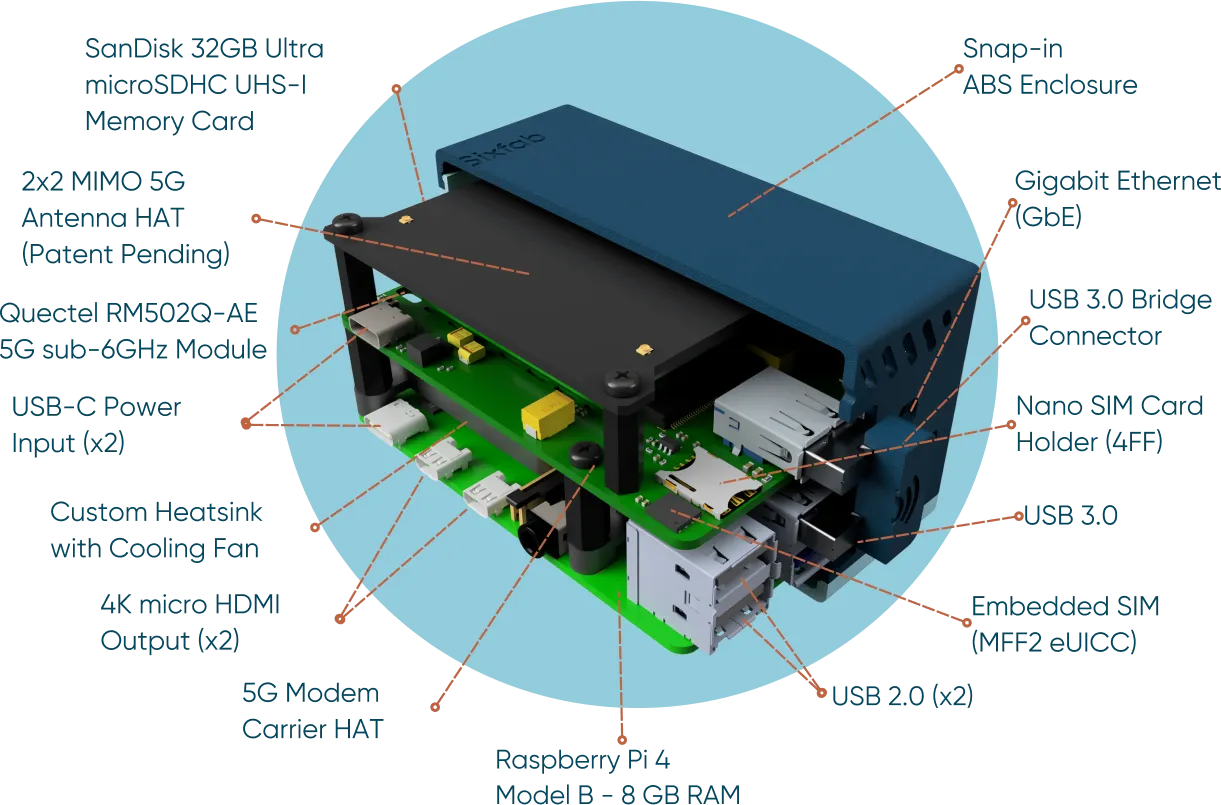
Jumpstart 5G Modem Carrier HAT
The detailed specifications of the Jumpstart 5G HAT are provided below.
Pinout
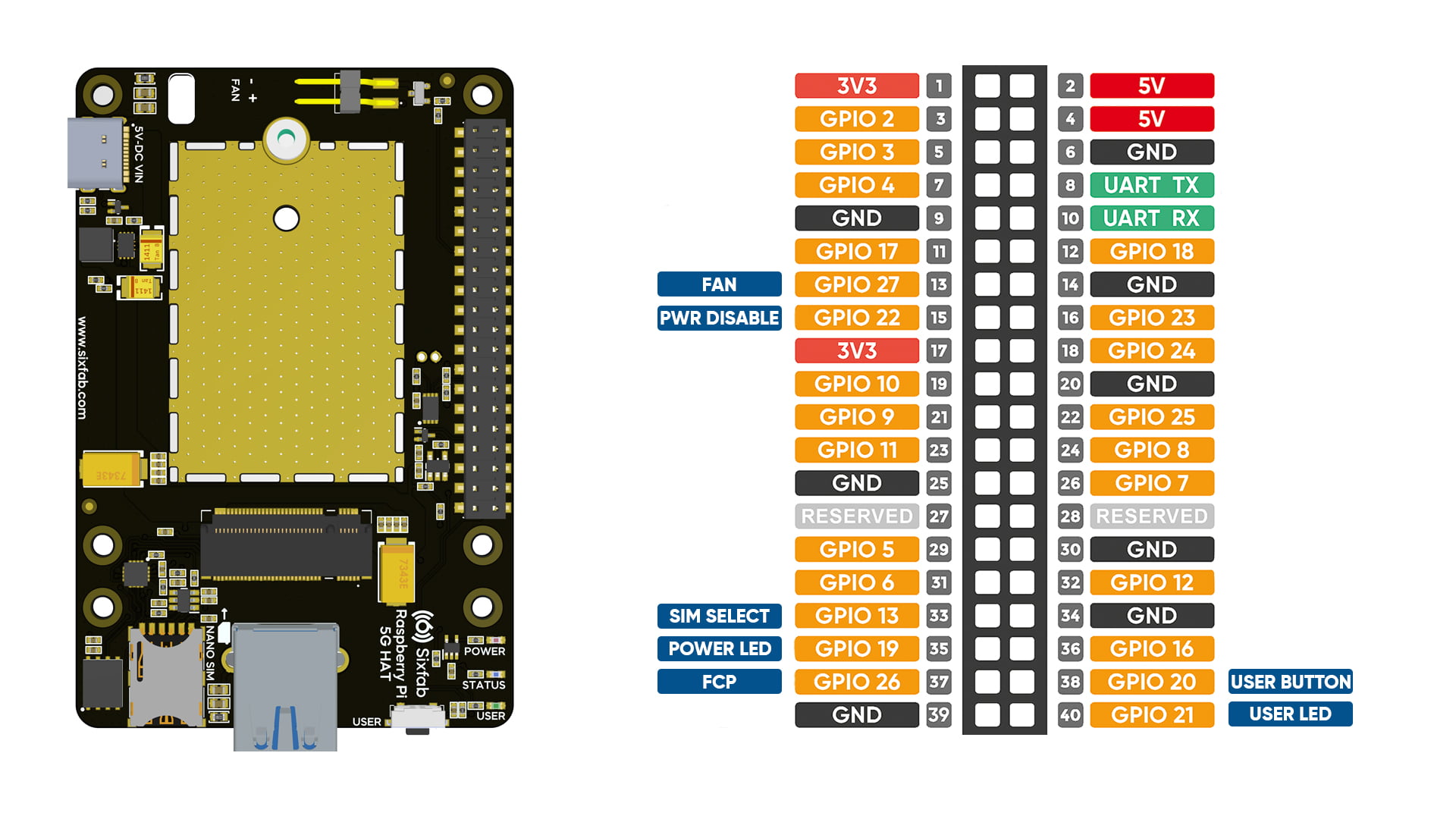
Pin Descriptions
Pin Number | BCM Pin | Pin Name | Description |
|---|---|---|---|
33 | GPIO13 | SIM Select | It is used to toggle between the nano SIM card and the embedded SIM. |
13 | GPIO27 | Fan On/Off - PWM Control | The pin turns on the FAN when set to HIGH. Default is LOW. PWM can control fan speed. In the included Raspberry Pi OS, fan is set to full speed at 60°C. At 50°C, fan turns off. |
37 | GPIO26 | 5G Module FCP | This pin controls power on/off of the module. Setting it to HIGH powers off the module after 10 seconds. Setting it to LOW initiates power-on sequence of the module and is fully functional after 50 seconds. Default state of the pin is LOW. |
40 | GPIO21 | User LED | When the pin is pulled HIGH, the LED lights up. |
38 | GPIO20 | User Button | This pin is pulled to the default HIGH state. When the button is pressed, the pin is pulled to the LOW. |
35 | GPIO19 | Power LED Off | If you want to turn off the Power LED, you can set this pin to HIGH. By default, the Power LED will always be on. |
15 | GPIO22 | Power Disable | Set the pin to HIGH to completely cut off power from the HAT, disabling power consumption. In case of module unresponsiveness, use this method to power cycle the HAT. Setting the pin to LOW supplies power to the HAT. Default state of the pin is LOW. |
Layout
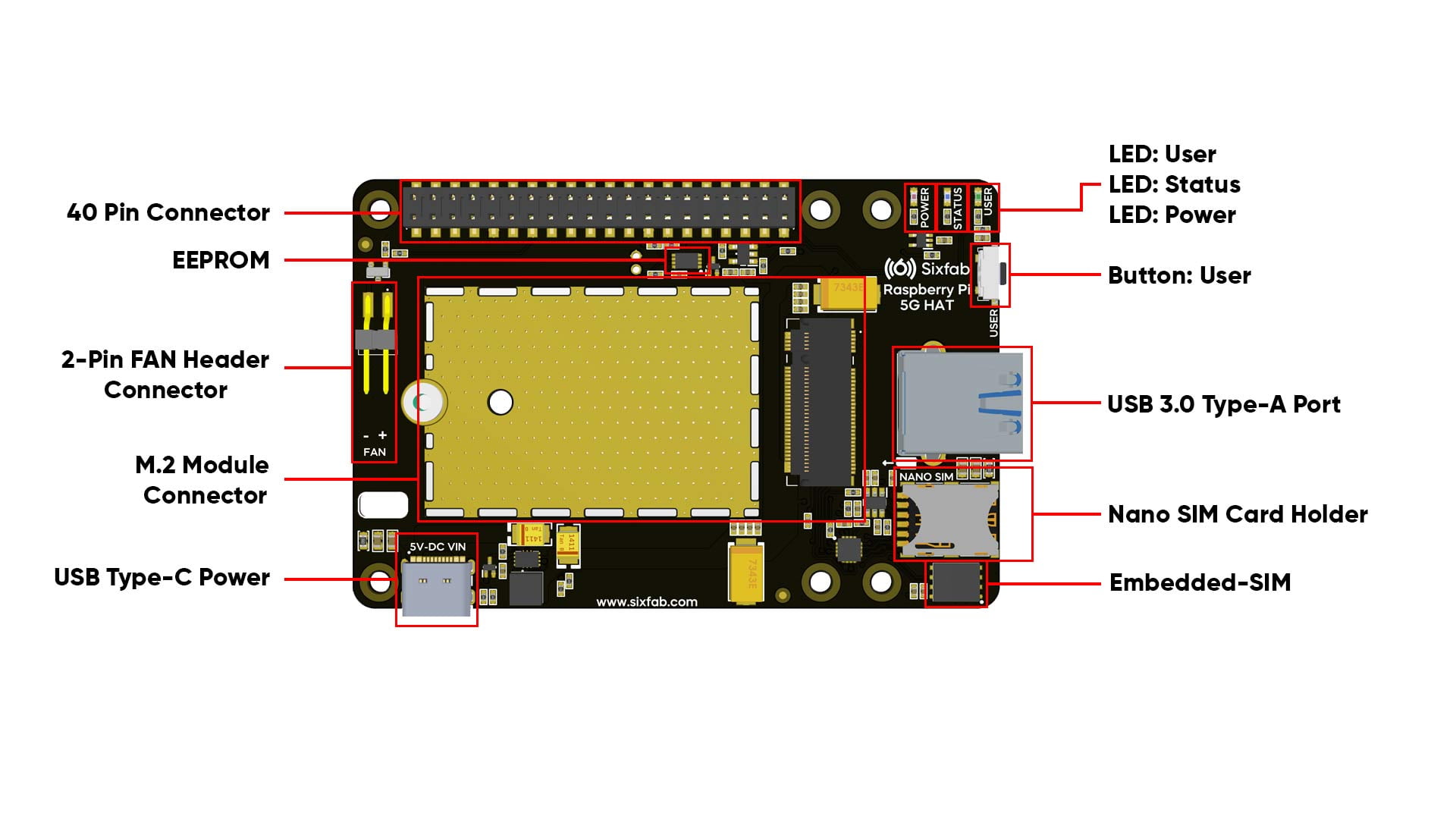
LEDs
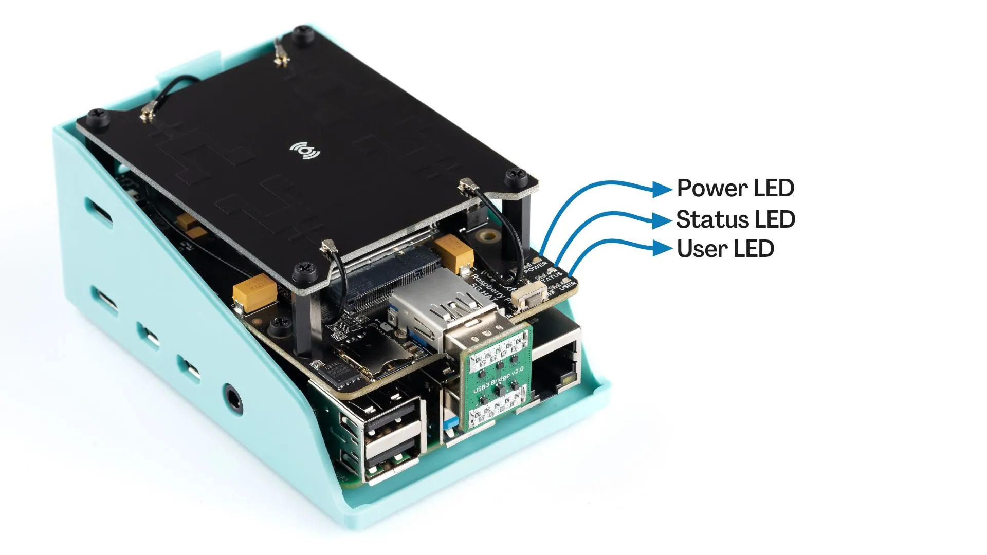
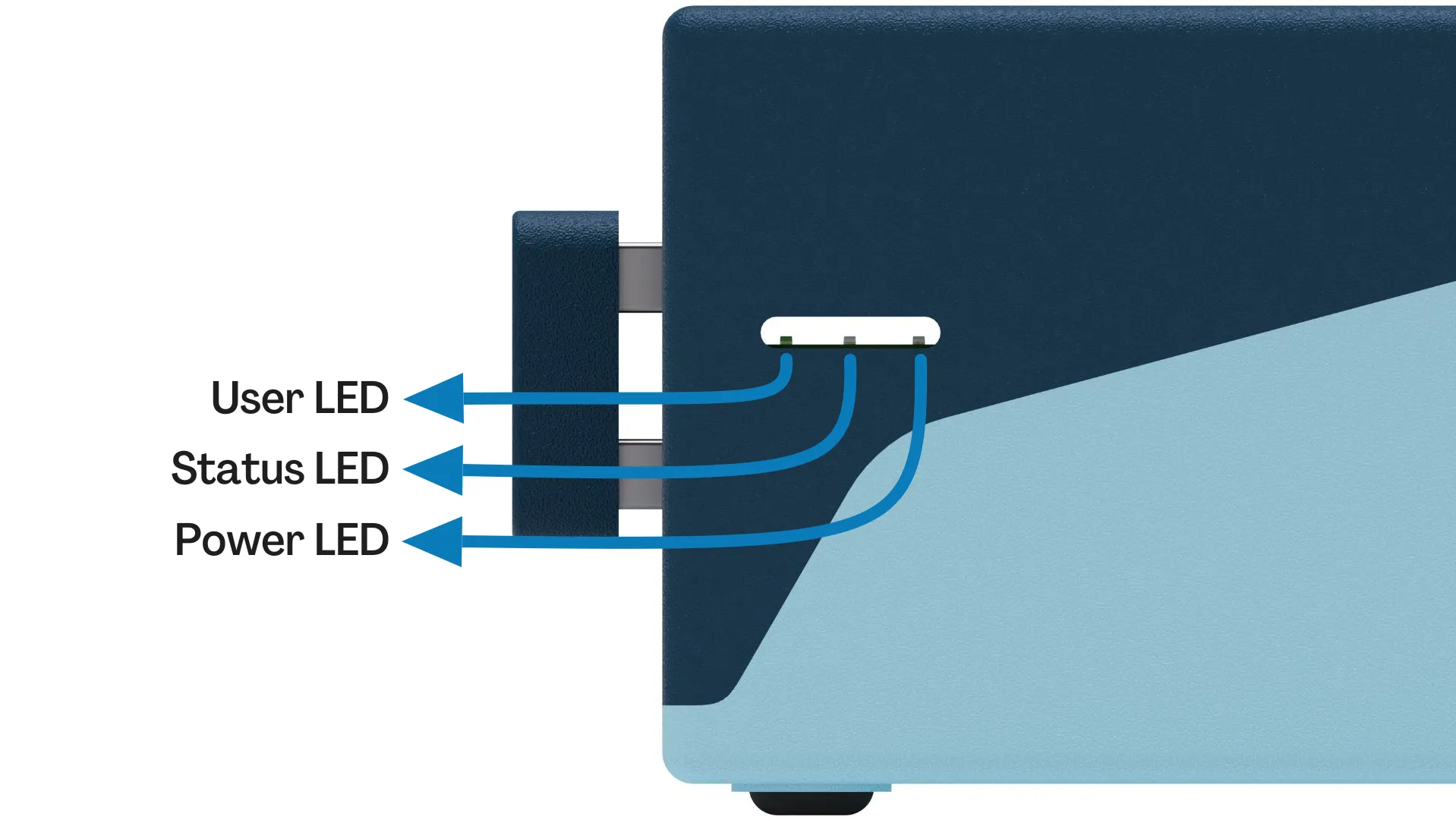
- POWER LED: The LED indicates power status of the HAT and can also be controlled via GPIO19. Refer to the pin descriptions table for instructions.
- STATUS LED: The LED indicates the RF function of the module. Turns on when RF Function is on. Turned off when the SIM is not powered or RF function is disabled.
- USER LED: It is a programmable user-LED that can be controlled from the GPIO21 of Raspberry Pi for debugging or just fun.
Buttons
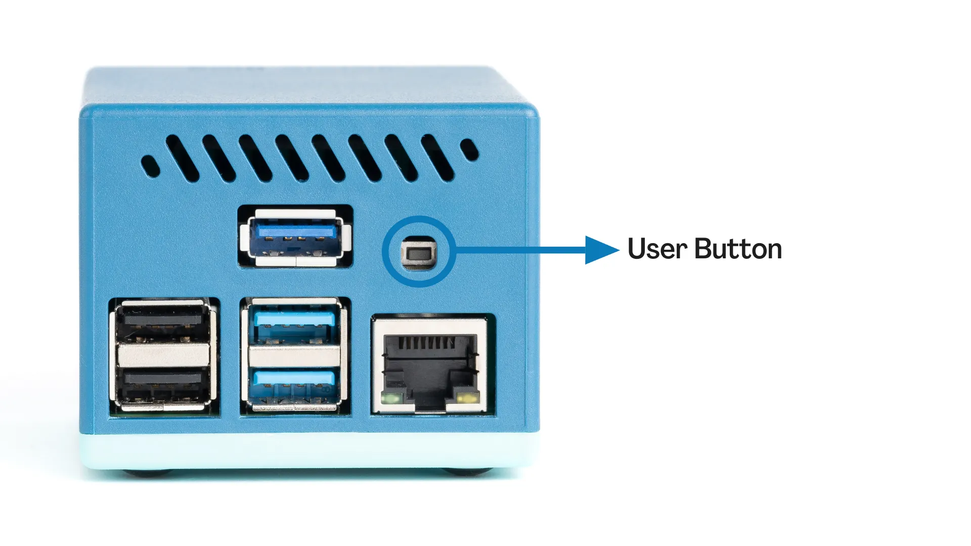
- User Button: It is a programmable user button that is connected to GPIO20. It reads HIGH by default.
5G Module
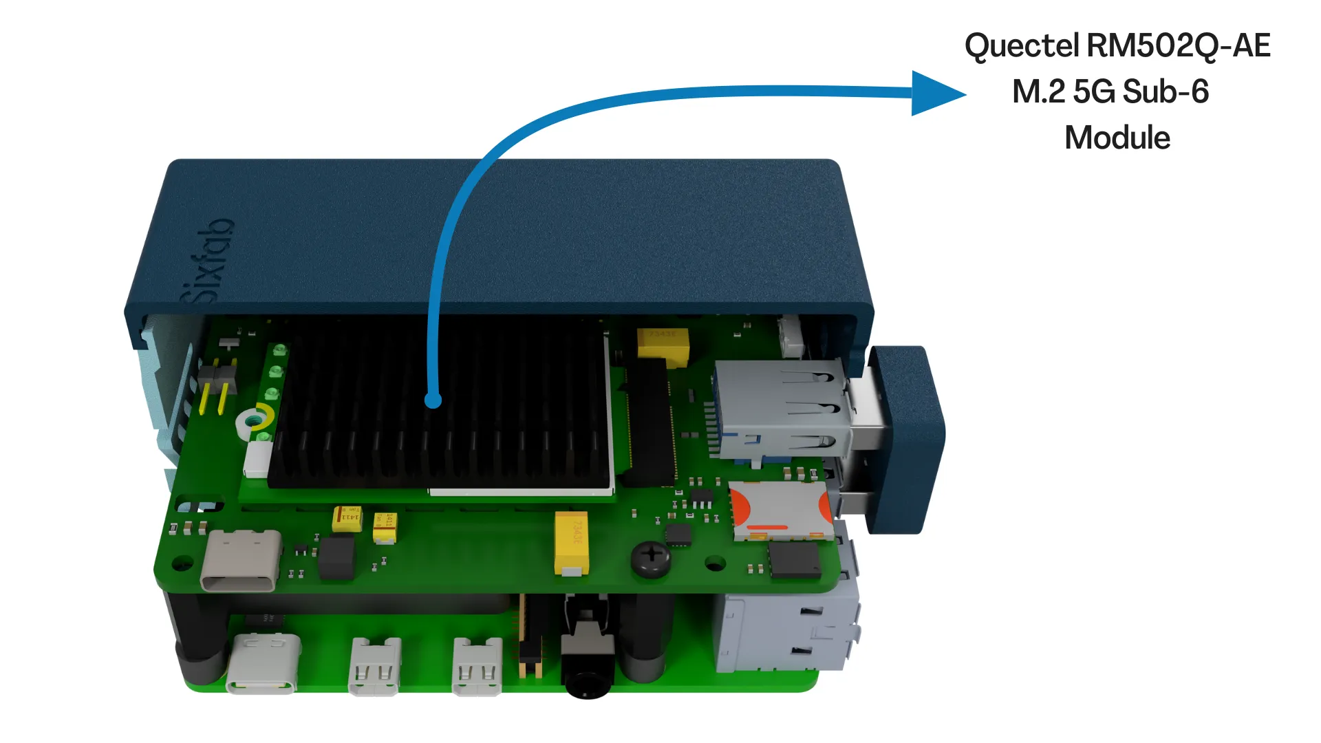
The module used in Jumpstart 5G is the Quectel M.2 5G Sub-6 RM502Q-AE module. It is attached to the HAT as shown below.
Frequency Bands
5G NR SA Bands: n41 (2469-2690MHz), n77 (3300-3800 MHz), n78 (3300-4200 MHz),n71(617-698 MHz)
5G NR NSA Bands: n41
Data Speed
5G SA Sub-6: Downlink 400 Mbps; Uplink 400 Mbps
5G NSA Sub-6: Downlink 400 Mbps; Uplink 400 Mbps
Region
Global
Network Protocols
TCP/UDP/FTP/HTTP/HTTPS/PING/SMS
Dimensions
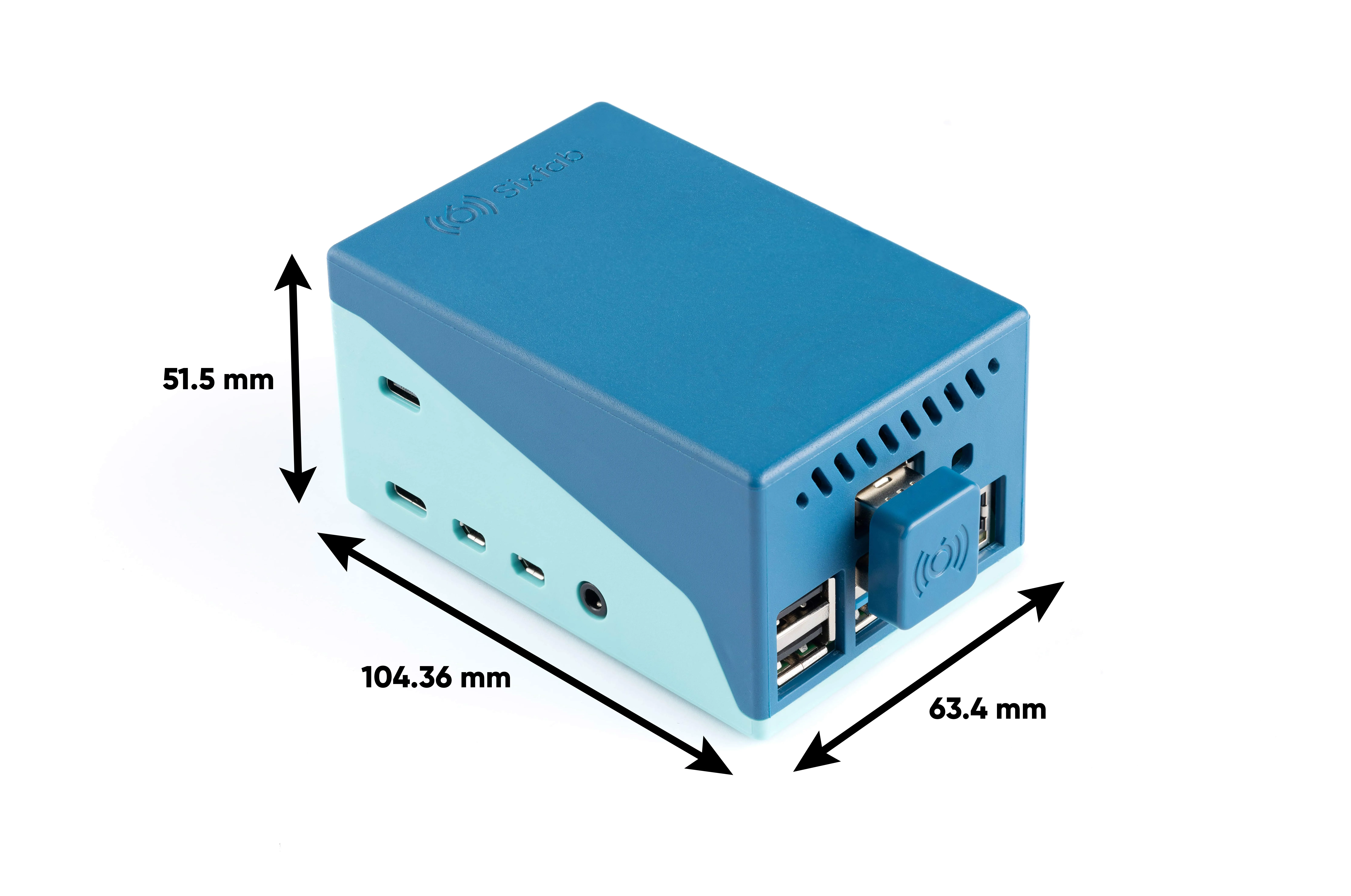
For detailed measurements of the product, please visit the documentation page.
Weight
The total weight of the product is 207.5 grams.
Raspberry Pi
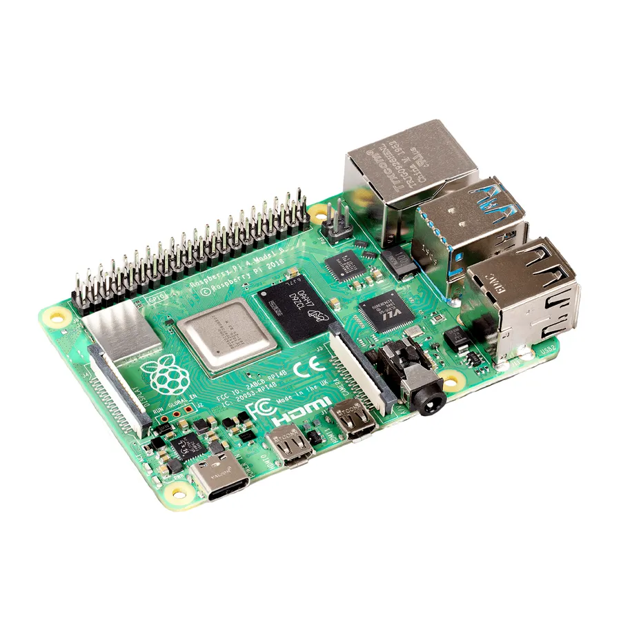
Official Raspberry Pi 4 8GB
Jumpstart 5G includes the official Raspberry Pi 4 8GB model. Here are its specifications:
- Broadcom BCM2711, Quad core Cortex-A72 (ARM v8) 64-bit SoC @ 1.8GHz
- 8GB LPDDR4-3200 SDRAM
- 2.4 GHz and 5.0 GHz IEEE 802.11ac wireless, Bluetooth 5.0, BLE
- Gigabit Ethernet
- 2 USB 3.0 ports; 2 USB 2.0 ports.
- 2 × micro-HDMI ports
- 2-lane MIPI DSI display port
- 2-lane MIPI CSI camera port
- 4-pole stereo audio and composite video port
- Micro-SD card slot for loading operating system and data storage
Power
Sixfab encourages to use of official power adapters for the product. The detailed power analysis of the product will be updated here soon.
USB Bridge
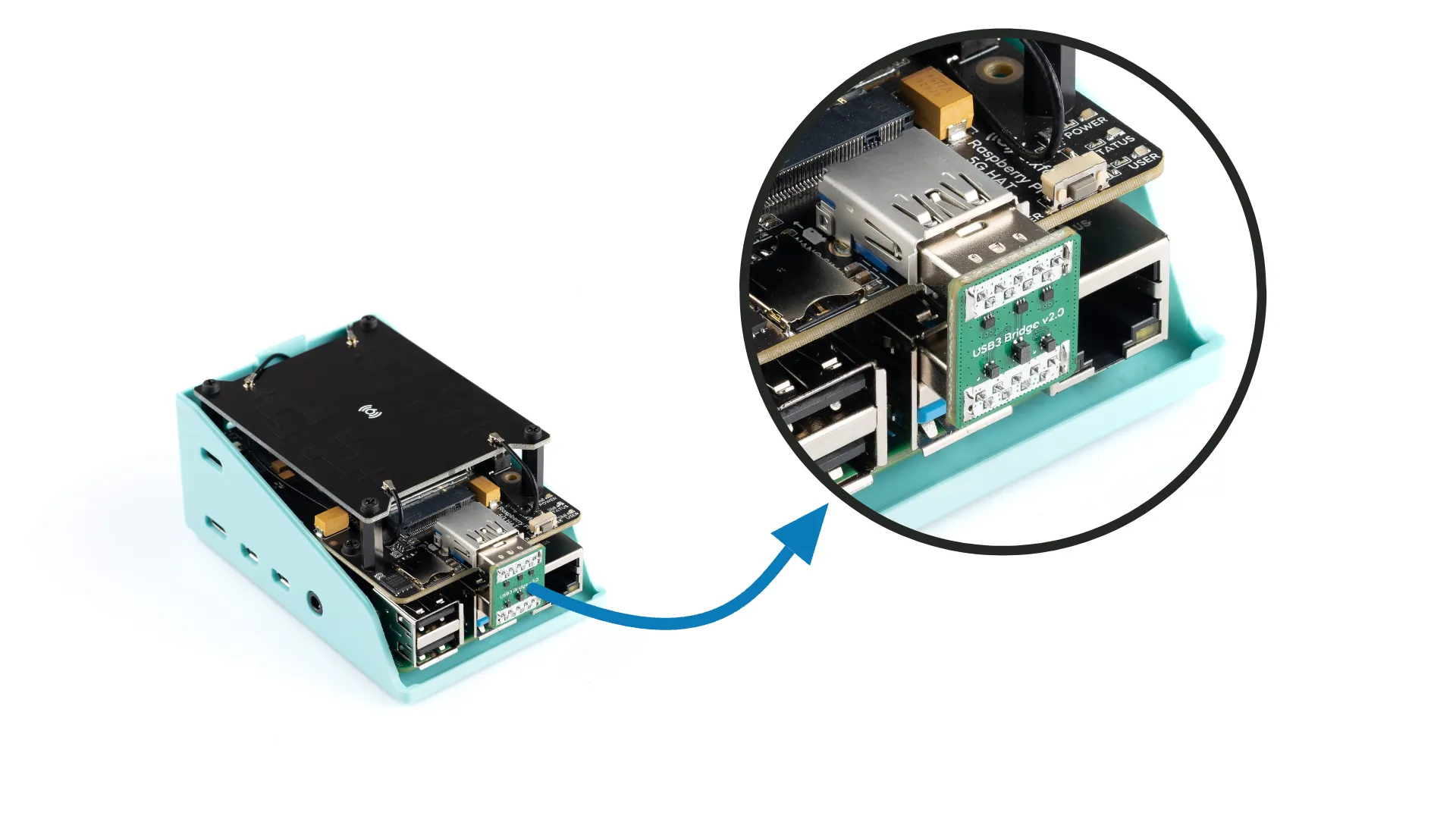
The USB Bridge serves the purpose of connecting the 5G module with the USB 3.0 port of the Raspberry Pi. This design choice was made in favor of using a USB cable, as it provides a robust, aesthetic, and space-saving solution. Rather than a standard straight cable connection, the USB Bridge has been specifically designed with filtering components to ensure faster and more efficient data transmission.
Antenna
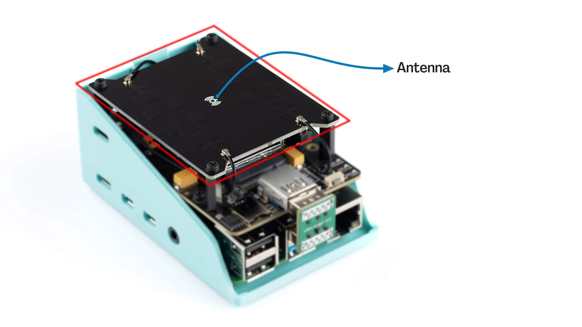
This antenna has been specifically designed and produced by Sixfab engineers, focusing on 5G bands and frequencies, exclusively for the Jumpstart 5G product.
The connections between the antenna and the 5G module are established using MHF4 connectors and custom-made MHF4 cables.
For in-depth technical specifications regarding the antenna, please consult the details provided below.
The designed 5G terminal antenna is 2x2 MIMO Micro-strip antenna, which operates over:
5G NR SA Bands: n41 (2469-2690MHz), n77 (3300-3800 MHz), n78 (3300-4200 MHz),n71(617-698 MHz)
5G NR NSA Bands: n41
Return Loss
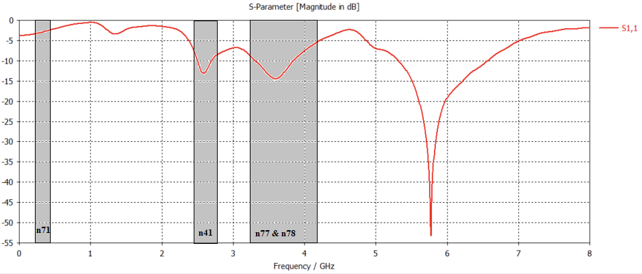
| Frequency (MHz) | 2579 | 3550 | 3750 | 600 |
| Value (dB) | -14.1 | -14.3 | -14.62 | -3 |
VSWR
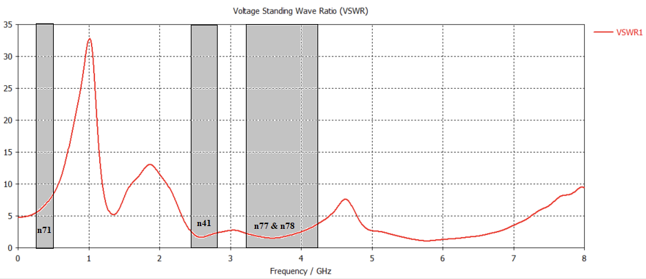
| Frequency (MHz) | 2579 | 3550 | 3750 | 600 |
| Value (dB) | 1.07:1 | 1.29:1 | 1.32:1 | 8.21:1 |
Ports Isolations
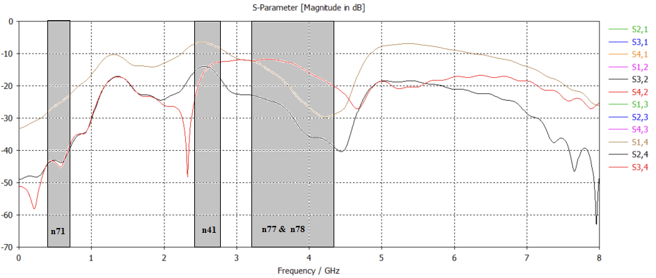
| Frequency (MHz) | 2579 | 3550 | 3750 | 600 |
| Avg. Ports Isolations | <-20 | <-25 | <-29 | <-40 |
Gains/Efficiencies/Polarizations
| Bands | Gains (dBi) | Efficiencies | Polarizations |
|---|---|---|---|
| N41 | 3.2 | 65% | Linear |
| N77 | 1.99 | 77% | Linear |
| N78 | 2.75 | 82% | Linear |
| N71 | 3.03 | 78% | Linear |
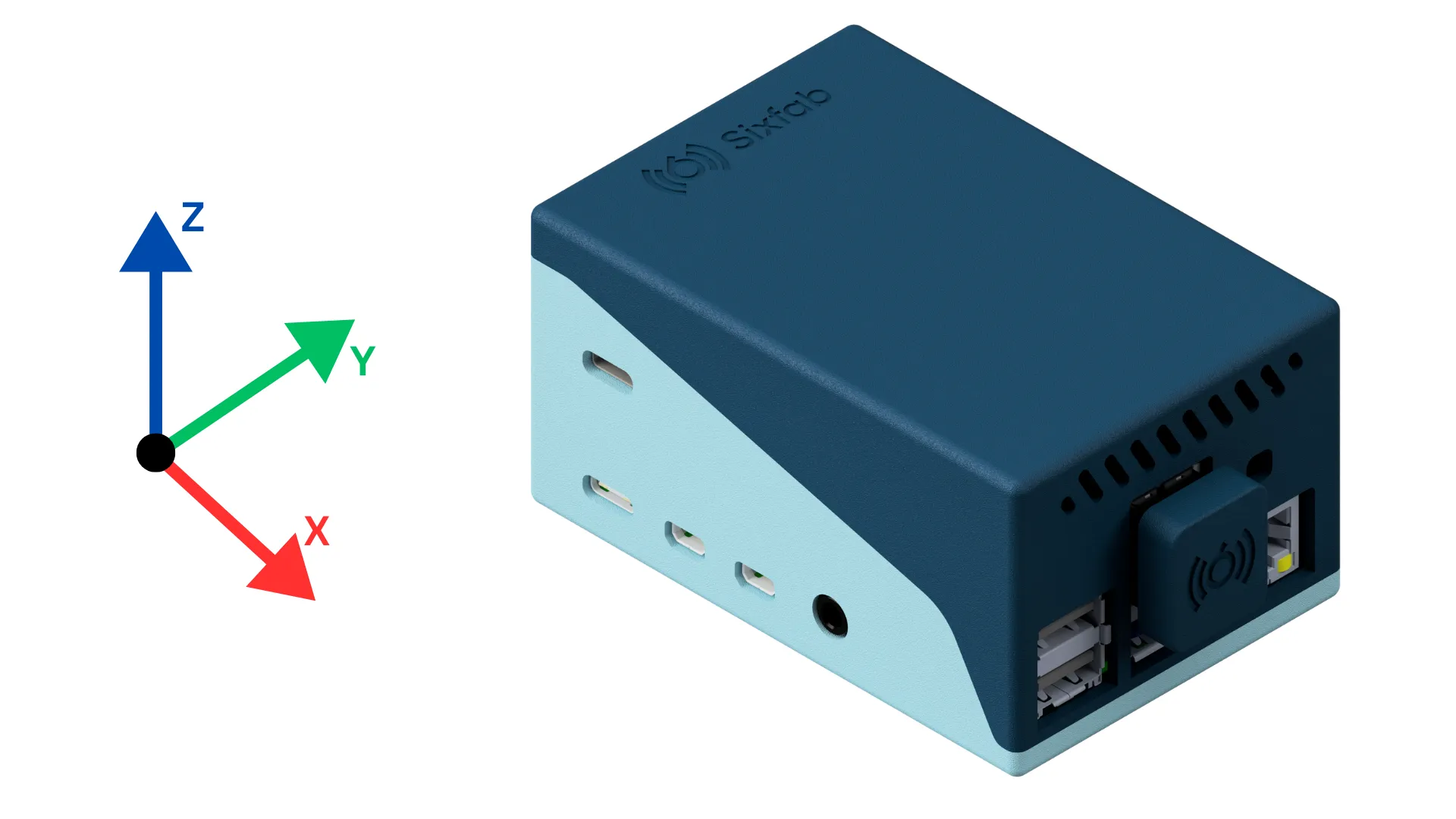
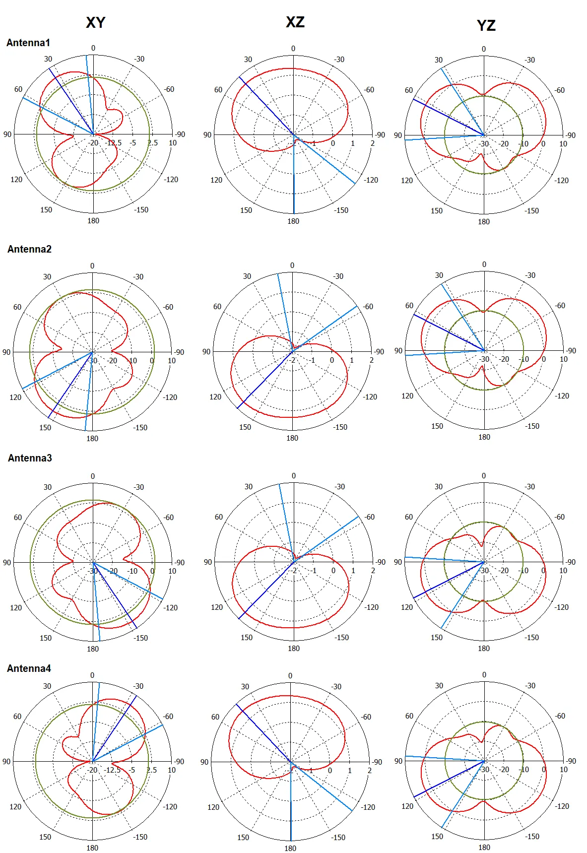
Propagation Patterns
Updated 6 days ago
