Technical Details
This section introduces the concepts and terms that are crucial for the understanding, implementation and use of Cellular IoT App Shield.
Band Details
| Specification | BG96 |
|---|---|
| LTE-FDD | B1/ B2/ B3/ B4/ B5/ B8/ B12/ B13/ B18/ B19/ B20/ B25①/ B26*/ B28 |
| LTE-TDD | B39 (for Cat M1 only) |
| eGPRS | 850/900/1800/1900Mhz |
| Embedded GNSS | GPS/Galileo/QZSS 1575.42±1.023 MHz GLONASS 1597.5~1605.8 MHz BeiDou 1561.098±2.046 MHz |
| Region | Global |
| Certification | GCF/Vodafone (Global) CE/Deutsche Telekom (Europe) AT&T/ FCC/ PTCRB/T-Mobile /Sprint (North America) RCM/Telstra (Australia) IC/Telus/BELL (Canada) Telefonica (Spain) JATE/KDDI/SoftBank/TELEC/DOCOMO (Japan) KC/SKT/LGU+* (Korea) IFETEL (Mexico) IMDA (Singapore) NCC (Taiwan) CCC (China) |
Warnings
- ① LTE B25 will be supported on BG96 with R1.2 hardware version.
- *Under Development
Connection Types
USB: If you don't want to occupy the UART port on the Raspberry Pi, just plug the shield via micro USB to Raspberry Pi. You can start to send and receive AT commands, transmit data, output GNSS NEMA, debug and upgrade firmware over the USB connection. It supports USB drivers for Windows, Linux, and Android. Details can be found in the drivers section.
UART: The UART pins will be available to use, with 3.3V power domain, directly connected to the UART port of Raspberry Pi. It can be used for data transmission and AT command communication with 115200bps baud rate. The default data frame format is 8N1 (8 data bits, no parity, 1 stop bit). This port does not provide GNSS data. The GNSS data can be gathered only over the USB.
To use the UART follow the steps mentioned in the UART Configuration guide.
Data Speeds
- Cat M1: Max. 375Kbps (Downlink), Max 375Kbps (Uplink)
- Cat NB1: Max. 32Kbps (DL), Max. 70Kbps (UL)
- EDGE: Max. 296Kbps (DL), Max. 236.8Kbps (UL)
- GPRS: Max. 107Kbps (DL), Max. 85.6Kbps (UL)
SMS
Point-to-point MO and MT
SMS Cell Broadcast
Text and PDU mode
Enhanced Features
- GNSS: GPS, GLONASS, BeiDou/Compass, Galileo, QZSS
- Firmware Upgrade: via USB interface
- DFOTA: Delta Firmware Upgrade Over the Air
- Audio Record/Play
- For the best working condition, use at least a 2A adapter or power source.
- We don’t recommend the usage of long and low-quality micro USB cables between Cellular IoT Application Shield and Raspberry Pi. It causes data and power loss.
- Do not apply higher voltages and currents than those specified absolute electrical values for sensor inputs and relay connections.
Pinout

Pin Descriptions
| Pin Number | BCM Pin | Pin Name | Description |
|---|---|---|---|
| 2 | 5V | 5V PWR | This pin is connected to the 5V power net. |
| 3 | GPIO 2 | SDA | I2C Serial Data |
| 4 | 5V | 5V PWR | This pin is connected to the 5V power net. |
| 5 | GPIO 3 | SCL | I2C Serial Data |
| 7 | GPIO 4 | 1-WIRE | Data line for communicate with 1-Wire sensors. |
| 8 | UART RX | BG96 TX | This pin functions as the serial data input to the module for UART communication. |
| 10 | UART TX | BG96 RX | This pin functions as the serial data output from the module for UART communication |
| 11 | GPIO 17 | RELAY | Relay control pin. When this pin is HIGH state, relay is operated.(Common and NO are connected.) |
| 12 | GPIO 18 | IN-2 | When the voltage in the range 3.3-12V(max 15V!) is applied from the IN-2 input, this pin goes to LOW state. Default state is HIGH(pulled-up). |
| 13 | GPIO 27 | USER LED | Active HIGH, to switch on the USER LED, the pin's state should be HIGH. |
| 18 | GPIO 24 | USER BUTTON | This pin normally pulled-down to ground. When button is pressed, pin switches to LOW. |
| 19 | GPIO 10 | IN-1 | When the voltage in the range 3.3-12V(max 15V!) is applied from the IN-1 input, this pin goes to LOW state. Default state is HIGH(pulled-up). |
| 23 | GPIO 11 | BG96 PWRKEY | The module can be turned on by driving the pin BG96 PWRKEY to a HIGH-level voltage more than 500ms then pulling it down. You can apply the same process to power down to the module if it already powered up. |
| 31 | GPIO 6 | BG96 APREADY | AP_READY will detect the sleep state of the host (can be configured to HIGH level or LOW level detection). Please refer to AT+QCFG=“apready” command for details. |
| 33 | GPIO 13 | BG96 RI | When BG96 has URC to report, RI signal will wake up the host. Please refer to Chapter 3.14 for details about RI behavior from BG96 Datasheet. |
| 37 | GPIO 26 | BG96 POWER ENABLE | BG96 3.8V Power regulator control. Normally pulled-up, when this pin drove to LOW, BG96's power will cut off. |
| 38 | GPIO 20 | BG96 STATUS | The STATUS pin is used to indicate the operation status of BG96 module. It will output HIGH level when the module is powered on. |
| 6,9,14,25,30,34,39 | GND | GND | This pins are connected to ground. |
Electrical Characteristics of Pins
| Pin Number | BCM Pin | Pin Name | Description | Min | Typ. | Max. | Unit |
|---|---|---|---|---|---|---|---|
| 2 | 5V | 5V PWR | Power Supply | 4.8 | 5 | 5.25 | V |
| 3 | GPIO 2 | SDA | I2C Data | 3 | 3.3 | 3.6 | V |
| 4 | 5V | 5V PWR | Power Supply | 3 | 3.3 | 3.6 | V |
| 5 | GPIO 3 | SCL | I2C Clock | 3 | 3.3 | 3.6 | V |
| 7 | GPIO 4 | 1-WIRE | 1-Wire data | 3 | 3.3 | 3.6 | V |
| 8 | UART RX | BG96 TX | UART | 3 | 3.3 | 3.6 | V |
| 10 | UART TX | BG96 RX | UART | 3 | 3.3 | 3.6 | V |
| 11 | GPIO 17 | RELAY | Output | 3 | 3.3 | 3.6 | V |
| 12 | GPIO 18 | IN-2 | Input | 3 | 3.3 | 3.6 | V |
| 13 | GPIO 27 | USER LED | Output | 3 | 3.3 | 3.6 | V |
| 18 | GPIO 24 | USER BUTTON | Input | 3 | 3.3 | 3.6 | V |
| 19 | GPIO 10 | IN-1 | Input | 3 | 3.3 | 3.6 | V |
| 23 | GPIO 11 | BG96 PWRKEY | Output | 3 | 3.3 | 3.6 | V |
| 31 | GPIO 6 | BG96 APREADY | Input | 3 | 3.3 | 3.6 | V |
| 33 | GPIO 13 | BG96 RI | Input | 3 | 3.3 | 3.6 | V |
| 37 | GPIO 26 | BG96 POWER ENABLE | Output | 3 | 3.3 | 3.6 | V |
| 38 | GPIO 20 | BG96 STATUS | Input | 3 | 3.3 | 3.6 | V |
Layout

Dimension

LEDs
- POWER (PWR): When the shield is powered up, this RED led turns on.
- STATUS (STAT): While the module is powered up by driving PWRKEY(GPIO 11) to HIGH state or pushing the PWRKEY button, this RED led turns on.
- USER (USER): The GREEN user led can be controlled by driving the GPIO 27 pin.
- ENABLE(EN): This GREEN led shows the status of the power regulator of module is switched on or off. By default, the GPIO 26(ENABLE) pin is pulled up by hardware and the regulator juices the module. To shut down the regulator, this pin needs to be driven to LOW state.
- NETLIGHT (NETL) : This BLUE led indicates the status of the module. When the connection is established and data is being transmitted/received, this led will blink at special intervals. Please find the following chart for details:
| State | Network Status |
|---|---|
| Flicker slowly (200ms ON/1800ms OFF) | Network searching |
| Flicker slowly (1800ms ON/200ms OFF) | Idle |
| Flicker quickly (125ms ON/125ms OFF) | Data transfer is ongoing |
| Always high | Voice calling |
Buttons
- USER: This push button connected to GPIO24 and pulled up HIGH state by default. When you push the button, you will read LOW state from GPIO24.
- PWRKEY: When BG96 is in power off mode, it can be turned on to normal mode by pushing the PWRKEY button for at least 500ms.
- BOOT: Pushing this button can force the module to boot from USB port for firmware upgrade.
Sensors and I/O
3-axis 12-bit/8-bit Digital Accelerometer | MMA8452Q
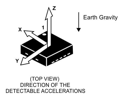
- The MMA8452Q is a smart, low-power, three-axis, capacitive, micromachine accelerometer with 12 bits of resolution. It has user selectable full scales of ±2 g/±4 g/±8 g with high-pass filtered data as well as non-filtered data available real-time.
- The accelerometer connected to Raspberry Pi via I2C. The I2C address is 0x1C.
- MMA8452Q's interrupt pins are not connected.
12-Bit Analog-to-digital Converter | ADS1015
- The ADS1015 is precision, low-power, 12-bit, analog-to-digital converter.
- Raspberry Pi can not measure analog inputs because it does not have internal ADC. However, with this external ADC, the ADS1015, you can read analog values with your Raspberry Pi.
- The ADC connected to Raspberry Pi via I2C. The I2C address is 0x49.
Ambient Light Sensor | ALS-PT19
- It's a phototransistor close responsively to the human eye spectrum, light to current.
- It's connected to ADC (ADS1015), because it has an analog output and Raspberry Pi can not read it directly.
- The sensor connected to AIN3 pin of ADS1015.
Temperature and Humidity Sensor | HDC1080
- The HDC1080 is a digital humidity sensor with an integrated temperature sensor that provides excellent measurement accuracy at very low power.
- Relative Humidity Accuracy ±2% (typical)
- Temperature Accuracy ±0.2°C (typical)
- The HDC1080 connected to Raspberry Pi via I2C. The I2C address is 0x40.
- The heat that produced by when R.Pi heats up may cause the sensor to display a few higher degrees than the ambient temperature.
Relay
- The relay for controlling high voltage and current.
- Relay control pin is GPIO17. When this pin is HIGH, relay is switched and connected C and NO pins. When GPIO17 is a LOW state or unused, it connects C and NC pins.
- This small form factor relay can handle up to 60W. Pushing the limits will harm the circuits and shield. Maximum contact ratings:
- 12V DC - 5A
- 24V DC - 2.5A
- 120V AC - 0.5A
- 220V AC - 0.25A
Isolated Inputs
- Two isolated by optocouplers inputs available on the shield. Recommended max. The GPIO voltage level of Raspberry Pi is 3.3V. Reading higher than 3.3V voltage inputs are harmful for your Pi and will definitely destroy the circuits.
- The upper limit of this inputs is 15V, between 3.3V and 15V is readable. GPIO pins are normally pulled up, when a voltage applied to isolated inputs, GPIO pins go LOW state.
- The input's (sensor, switch, etc.) ground must be connected to optocoupler's G input to complete isolated circuits.
GNSS and Debug(DBG) UART Inputs
GNSS: This header pins directly connected to BG96 GNSS output. They are not connected to the UART port of Raspberry Pi. You should connect to BG96 via USB to receive GNSS data. Thinking that these pins might be needed somehow, so we've taken them out as headers.
Debug (DBG): This DEBUG UART port belongs to BG96 and used for embedded firmware debugging of the module and log output.
External I2C Header
When you need to add an external I2C thing, you can use these I2C connectors. 3.3V VCC and GND pins provided too. It has a pull-up resistor.
1-Wire Header
There are lots of sensors which have 1-Wire connection standard (DS18B20 etc.) in the market. The 1-Wire connector has VCC, DATA and GND pins. With these pins, you can connect easily a 1-wire sensor. The data pin directly connected to GPIO4 and has a 4.7K pull-up resistor.