Physical Layout & I/O
Physical Layout & I/O
Pinouts, ports, connectors, and indicators on the ALPON X4 industrial edge computer. This reference covers every externally accessible interface, its electrical characteristics, and the GPIO mapping required to drive it from software.
The ALPON exposes three power inputs (USB-C PD, 9–30V DC screw terminal, optional PoE+), one 1 Gbps + one 100 Mbps Ethernet port, two USB 2.0 ports, an HDMI 2.0 display output (up to 4Kp30), an RJ45 GPIO Add-on port (I²C / UART / SPI, 3.3V logic), four LED indicators, two programmable push buttons, and two DIP switches for watchdog and boot/burn selection.
Device layout overview
The ALPON X4 enclosure is a fanless aluminum case measuring 111.16 × 99.9 × 33 mm, weighing approximately 457 g, rated IP40, and designed for -20°C to +60°C ambient operation. All I/O is distributed across the front and rear faces; the top face doubles as a passive cooling surface.
Front face (1–6)
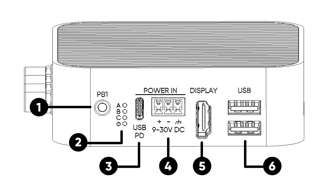
GPIO 5, active LOWRear face (7–11)
GPIO 6, active LOWEnclosure (12–14)
Mechanical specifications
Download the full 2D dimensional drawings for CAD integration: ALPON X4 Dimensions (PDF).
Power input
The ALPON X4 accepts power from three independent interfaces. Only one input should be connected at a time.
1. USB Type-C PD input
Sink-only USB-PD port. The device is powered by a USB PD-enabled Type-C adapter capable of delivering 27W or more. Use the adapter included in the package for guaranteed compatibility.
2. Screw terminal block (9–30V DC)
3-pin removable terminal accepting a wide DC input range for industrial power rails. Minimum supply rating: 30W at 12V or 24V. Observe polarity markings (+ / –) on the housing when wiring.
| Input Range | 9–30V DC |
| Power Rating | 27W minimum |
| Reverse Polarity | Hardware-protected |
| Connector | 3-pin removable screw terminal |
3. Power over Ethernet (PoE+)
Available only on PoE-variant SKUs. The PoE+ module cannot be added retroactively. PoE+ input is routed exclusively through the ETH/G port on PoE variants.
| Standard | IEEE 802.3at (PoE+ Class 4) |
| Input Voltage | 37–57V (typical 48V) |
| Power Budget | Up to 25W |
| Port | ETH/G (PoE variant only) |
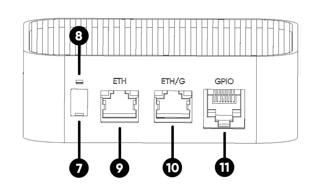
Ethernet ports
The ALPON X4 provides two Ethernet interfaces with distinct link speeds. Both ports use standard RJ45 connectors with integrated link/activity LEDs.
| Port | Speed | Notes |
|---|---|---|
ETH/G |
1 Gbps | Primary high-speed LAN port. On PoE variants, this port accepts PoE+ input. |
ETH |
100 Mbps | Secondary LAN port. Routed through a USB-to-Ethernet bridge on the CM4. |
USB ports
Two USB 2.0 High-Speed ports on the front face, connected directly to the Raspberry Pi CM4 USB controller. Ports are enumerated as native CM4 USB devices by the host OS.
| Port Count | 2× USB 2.0 (Type-A) |
| Max Speed | 480 Mbps (High-Speed) |
| Output Voltage | 5V DC |
| Combined Current Budget | 1A total across both ports |
| Overcurrent Behavior | Both ports cut off on overcurrent. Requires full reboot to restore. |
Display (HDMI)
Full-size HDMI 2.0 output routed from the CM4's primary display controller. Compatible with standard HDMI cables to any HDMI monitor or capture device.
| Port Standard | HDMI 2.0 (Type A, full size) |
| Maximum Resolution | 4K @ 30Hz (4Kp30) |
| Audio | Carried over HDMI |
GPIO Add-on port (RJ45)
The GPIO port exposes six configurable CM4 pins over an RJ45 connector, providing I²C, UART, and SPI to ALPON Edge Add-on modules. Signals are routed through a voltage-level converter for stable long-cable runs, with built-in ESD protection.
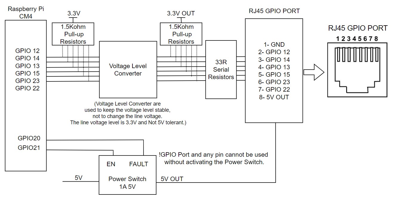
Pin assignment
| RJ45 Pin | CM4 GPIO | Alternate Functions |
|---|---|---|
| 1 | GND | Ground |
| 2 | GPIO 12 | SPI5_CSn[0], UART4_TX, I2C2_SDA |
| 3 | GPIO 14 | SPI5_SIO[0], UART0_TX, I2C3_SDA |
| 4 | GPIO 13 | SPI5_SIO[1], UART4_RX, I2C2_SCL |
| 5 | GPIO 15 | SPI5_SCLK, UART0_RX, I2C3_SCL |
| 6 | GPIO 23 | I2C3_SCL |
| 7 | GPIO 22 | I2C3_SDA |
| 8 | 5V OUT | 5V power output, max. 1A (5W). Gated by power switch (GPIO 21). |
Electrical characteristics
| Signal Voltage | 3.3V logic (with level converter and ESD protection) |
| 5V Tolerance | Not 5V tolerant |
| Pull-up Resistors | 1 kΩ hardware pull-up on every signal pin |
| Power Output | 5V @ 1A maximum (5W) |
| Power Switch Enable | GPIO 21 — must be set HIGH before I/O |
| Fault Detection | GPIO 20 — HIGH normally, LOW on overcurrent / overtemperature / reverse voltage |
Power-switch control
The port's 5V supply and all signal I/O are gated by an on-board power switch. At boot, the port is inactive by default. To activate the port, drive GPIO 21 HIGH from software before any communication begins.
import RPi.GPIO as GPIO

GPIO.setmode(GPIO.BCM)
GPIO.setup(21, GPIO.OUT)   # ADDON_PWS_EN
GPIO.setup(20, GPIO.IN)    # ADDON_PWS_FAULT

# Enable the GPIO Add-on port
GPIO.output(21, GPIO.HIGH)

# Check for fault condition
if GPIO.input(20) == GPIO.LOW:
    print("Fault detected on Add-on port")
If an overcurrent, overtemperature, or reverse voltage condition is detected on the 5V rail, the port enters protection mode. GPIO 20 reads LOW while the fault persists and returns HIGH once the condition clears.
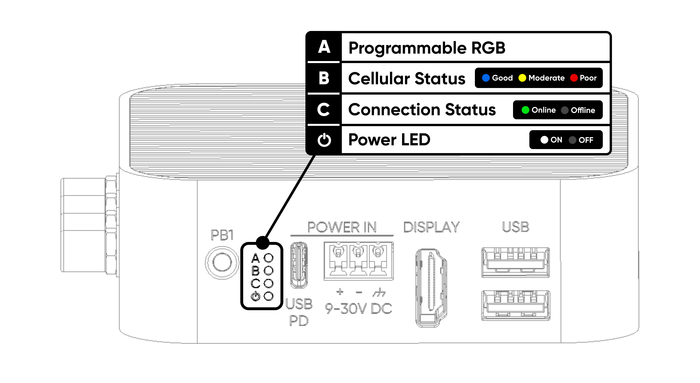
LED indicators
The ALPON X4 has four LED indicators on the front face. One RGB LED is reserved for user applications; the remaining three are driven by the ALPON Cloud platform and firmware-level services.
| # | Label | Description |
|---|---|---|
| A | Programmable RGB | Freely programmable via I²C. Connected to the TCA6408A I/O expander at address 0x20. Pins: P2 Red, P3 Green, P4 Blue. |
| B | Cellular Status | Cellular connection quality. Red = poor, Yellow = moderate, Blue = good. |
| C | Connection Status | Device online status. Lights green when accessible via Sixfab Connect. |
| ⏻ | Power Status | Power LED. Turns white 3 seconds after the device powers on. |
RGB LED control (I²C)
The RGB LED is driven by the TCA6408A I/O expander, connected to the CM4 on the I2C1 bus (GPIO 2 SDA, GPIO 3 SCL). The chip address is 0x20.
| Controller | TCA6408A I/O expander |
| I²C Bus | I2C1 (GPIO 2 SDA, GPIO 3 SCL) |
| I²C Address | 0x20 |
| Red Pin | P2 |
| Green Pin | P3 |
| Blue Pin | P4 |
| Logic | Active LOW (write 0 to illuminate) |
Reference implementation: RGB LED Python script on GitHub Gist.
Push buttons
The ALPON X4 provides two user-configurable hardware buttons. Both are wired to the CM4 GPIO with internal pull-up resistors, so each GPIO reads HIGH while the button is released and pulls LOW when pressed.
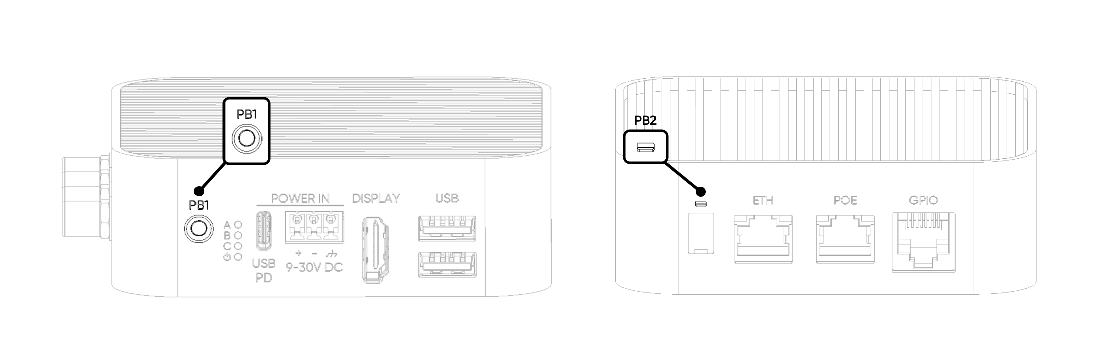
| Button | CM4 GPIO | Default behavior |
|---|---|---|
| PB1 (User) | GPIO 5 | HIGH (pull-up). LOW when pressed. Free for user application. |
| PB2 (Reset) | GPIO 6 | HIGH (pull-up). LOW when pressed. Reserved for reset/user-assigned action. |
import RPi.GPIO as GPIO

GPIO.setmode(GPIO.BCM)
GPIO.setup(5, GPIO.IN, pull_up_down=GPIO.PUD_UP)   # PB1
GPIO.setup(6, GPIO.IN, pull_up_down=GPIO.PUD_UP)   # PB2

def on_pb1(channel):
    print("PB1 pressed")

GPIO.add_event_detect(5, GPIO.FALLING, callback=on_pb1, bouncetime=200)
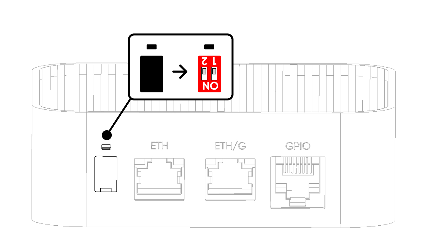
Watchdog & Boot/Burn DIP switches
Two DIP switches on the rear face control the hardware watchdog and the CM4 boot mode. Both ship OFF by default and should remain OFF during normal operation. The switches are covered with a silicone cap; use a pointed tool to gently lift the cap from its notch.
| Position | SW1 — Watchdog | SW2 — Boot/Burn |
|---|---|---|
| ON | Watchdog Disabled | Burn (Image Flash Mode) |
| OFF (Default) | Watchdog Enabled | Boot (Operating Mode) |
SW1 – Hardware watchdog
The hardware watchdog monitors system liveness independently of the operating system. When enabled (SW1 OFF), the CM4 must toggle the watchdog trigger line at regular intervals. If no trigger arrives within the timeout window, the watchdog cuts all power to the device, waits briefly, then re-applies power to force a cold reboot.
SW2 – Boot / Burn mode
SW2 selects between normal operation (Boot) and CM4 image flashing over USB-C (Burn). In Burn mode, the USB-C port exposes the CM4's flashing interface to a host PC running rpiboot.
Antenna connectors
Four SMA connectors on the top face provide external antenna access for cellular, GNSS, and Wi-Fi / Bluetooth radios. All connectors are standard SMA female; compatible with the bundled antennas or third-party antennas with SMA male terminations.
| Connector | Radio | Role |
|---|---|---|
| LTE Main | 4G / LTE Cat 4 | Primary cellular antenna |
| LTE Diversity | 4G / LTE Cat 4 | Receive-diversity antenna (improves signal quality) |
| GNSS | GPS / GNSS | Positioning antenna (active, 3.3V bias) |
| Wi-Fi / BLE | Wi-Fi 2.4/5 GHz + Bluetooth 5.0 | Shared Wi-Fi and BLE antenna |
I/O topology
The ALPON X4's interfaces attach to the Raspberry Pi CM4 through native SoC controllers and a small number of bridge chips. The table below summarizes the primary data paths.
| Interface | CM4 Connection | Notes |
|---|---|---|
| USB 2.0 Ports | Native CM4 USB 2.0 | Direct connection; shared 1A output budget |
| ETH/G (1 Gbps) | Native Ethernet MAC | Carries PoE+ on PoE variants |
| ETH (100 Mbps) | USB 2.0 → USB-GbE bridge | Secondary LAN via onboard USB-to-Ethernet controller |
| HDMI Display | CM4 HDMI 0 | Up to 4Kp30 |
| LEDs | I²C1 → TCA6408A @ 0x20 | Expander-driven |
| GPIO Add-on Port | CM4 GPIO 12–15, 22, 23 | Gated by GPIO 21 power switch |
| User Buttons | CM4 GPIO 5, GPIO 6 | Internal pull-up, active LOW |
Where to next
Updated about 4 hours ago