Physical Layout & I/O
Physical Layout & I/O
Pinouts, ports, connectors, and indicators on the ALPON — a compact industrial edge AI computer built on Raspberry Pi CM5 with a 25 TOPS DEEPX NPU. This reference covers every externally accessible interface, its electrical characteristics, and the GPIO mapping required to drive it from software.
The ALPON exposes three power inputs (USB-C PD, 12–32V DC screw terminal, optional PoE+), two 1 Gbps Ethernet ports, two USB 3.0 ports, an HDMI 2.0 display output, a MIPI-CSI camera port over Mini HDMI, an RJ45 GPIO Add-on port (I²C / UART / SPI, 3.3V logic), four LED indicators, two programmable push buttons, and two DIP switches for watchdog and boot/burn selection.
Device layout overview
The ALPON enclosure is a fanless aluminum case measuring 100 × 100 × 45 mm, weighing approximately 457 g, rated IP40, and designed for -20°C to +60°C ambient operation. All I/O is distributed across the front and rear faces; the top face doubles as a passive cooling surface.

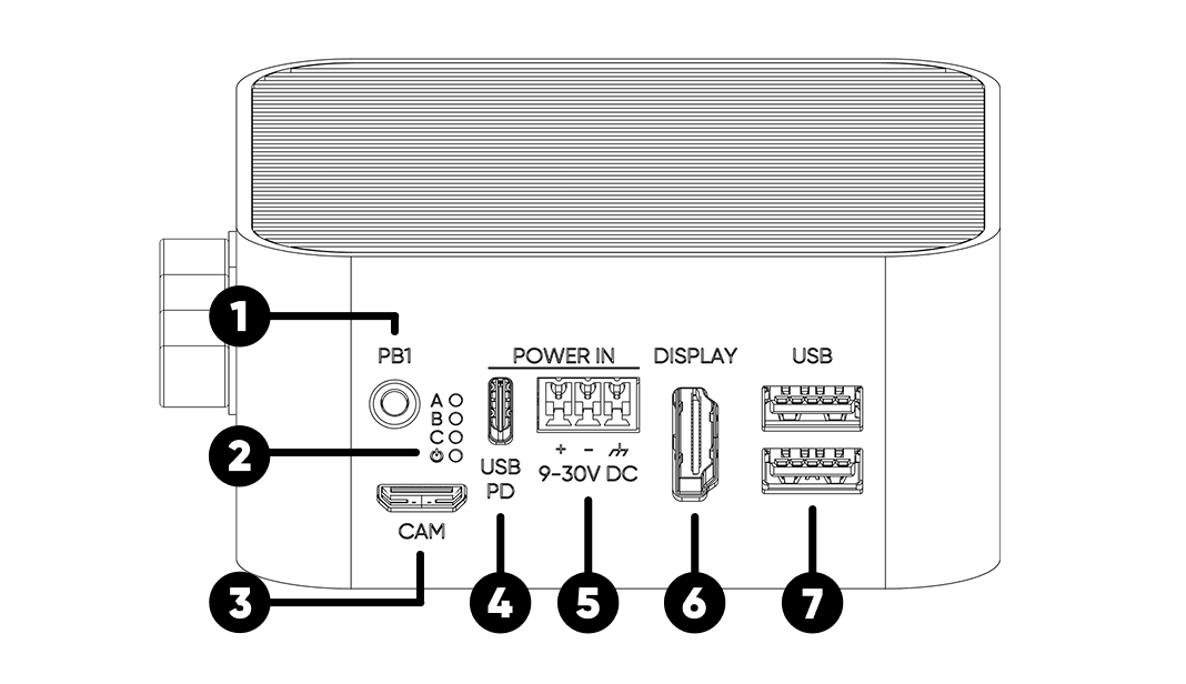
Front face (1–7)
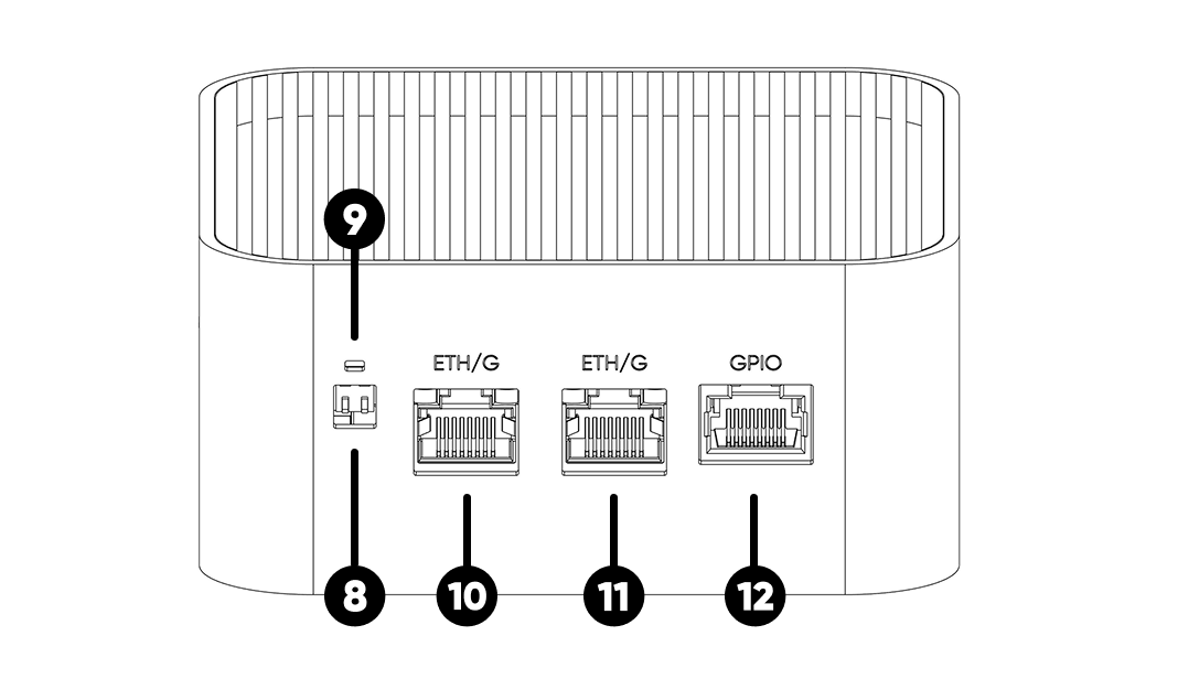
Rear face (8–12)
Enclosure (13–15)
Mechanical specifications
Download the full 2D dimensional drawings for CAD integration: ALPON X5 AI Dimensions (PDF).
Power input
The ALPON accepts power from three independent interfaces. There is no hardcoded priority between inputs — the device always draws from the source with the highest voltage. All three inputs pass through ideal diodes on the main board, so simultaneous connection is tolerated but not recommended.
1. USB Type-C PD Input
Sink-only USB-PD port — does not provide USB data or power output during normal operation. Works as a USB data input only in Burn (image flashing) mode.
| Recommended Adapter | 27 W minimum at 15 V; 45 W adapter recommended for full-load AI workloads |
| Supported PD Profiles | 12 V / ≥2.25 A (recommended 12.0V / 3.75A) 15 V / ≥1.8 A (recommended 15.0V / 3.0A) |
| PD Controller | CYPD3177-24LQXQ |
| Mode | Sink only — no output |
| Data Mode | USB data available only while SW2 = Burn |
2. Screw Terminal Block (12–32V DC)
The recommended input for industrial edge computing deployments. Terminal block includes hardware-level reverse-polarity protection; the device will not be damaged by swapped + / − wiring, but it also will not power on.
| Input Voltage Range | 12 V – 32 V DC |
| Minimum Power | 27 W |
| Reverse Polarity Protection | Yes (hardware) |
| Pinout (3-pin terminal) | Pin 1: Chassis Ground · Pin 2: Negative (−) · Pin 3: Positive (+) |
3. Power over Ethernet (PoE+)
PoE+ is available only on PoE-variant SKUs and cannot be added after manufacture. When present, PoE+ is wired to ETHERNET 0. ETHERNET 1 does not accept PoE.
| Standard | IEEE 802.3at · PoE+ Class 4 |
| Input Voltage Range | 37 V – 57 V |
| Maximum Delivered Power | 25 W |
| Supported Port | ETHERNET 0 only |
Restricted Mode
If any power source drops below 12 V (for example, a 5 V supply on USB-C), the device automatically enters Restricted Mode — a protective state that keeps the system running on minimal power without risking brownout damage to the NPU or SSD.
- CM5 Compute Module
- LTE Modem
- ETHERNET 0
- ETHERNET 1
- USB Ports
- PCIe Interface (NVMe SSD + AI Accelerator)
- GPIO Add-on Port
- Camera Port
Power consumption
Measured subsystem power draw at idle, 50% load, and full load. A dash (–) indicates the subsystem draws negligible standalone power at that level.
| Subsystem | Idle (W) | 50% Load (W) | Full Load (W) |
|---|---|---|---|
| CM5 Compute Module | 4 | 7 | 10 |
| LTE Modem | 1 | 3 | 5 |
| Voltage Regulators | 1 | 2 | 3 |
| GPIO Add-on Port | – | – | 5 |
| USB 3.0 Ports | – | – | 9 |
| Camera Port | – | 1.4 | 2.5 |
| DEEPX AI Accelerator | 1 | 3 | 5 |
| NVMe SSD | 1 | 3 | 6 |
| Total | 8 | 19.4 | 45.5 |
Values are approximate. Actual consumption varies with workload, connected peripherals, and ambient temperature.
Ethernet ports
Two Gigabit (1 Gbps) RJ45 Ethernet ports with different electrical topologies. Use both simultaneously for WAN + LAN routing, dual-NIC redundancy, or network isolation between trusted and field segments.
Direct native Ethernet port on the CM5. Carries PoE+ power injection on variants that include the PoE module.
USB-to-Gigabit bridge via RTL8153B. Shares the 5 Gbps USB 3.0 bus with one of the front USB ports.
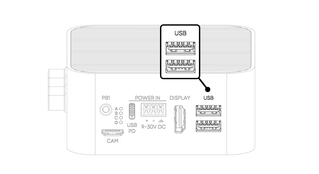
USB ports
Two USB 3.0 ports rated at 5 Gbps each, with a combined power budget of 1.8 A (5V) across both.
| USB 3.0 Port 1 | Native CM5 USB 3.0 — direct connection |
| USB 3.0 Port 2 | Routed via TUSB8020 USB hub (shares upstream with ETHERNET 1) |
| Shared Power Budget | 1800 mA total across both ports (5 V) |
| Overcurrent Protection | Hardware current limiter with thermal shutdown |
| Fault Reporting | Fault routed to TUSB8020; OS-level syslog entry on trip |
| Power Recovery | Automatic when fault clears — no reboot required |
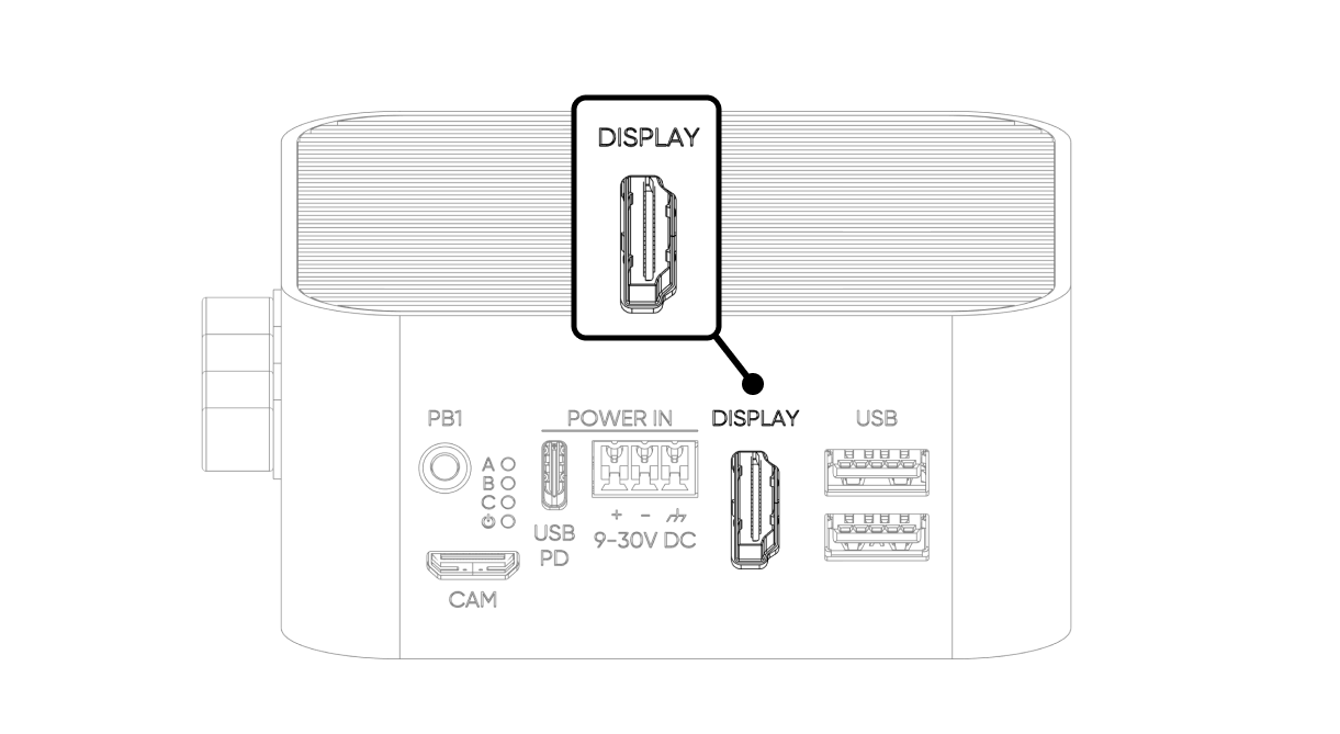
Display (HDMI 2.0)
Single HDMI 2.0 port driven directly by the CM5. Supports up to 4K @ 60 Hz with HDR and pass-through audio. For supported refresh-rate and color-depth combinations, refer to the Raspberry Pi CM5 datasheet.
| Standard | HDMI 2.0 |
| Maximum Resolution | 4K @ 60 Hz (4Kp60) |
| HDR | Supported |
| Video Decoder | 4Kp60 HEVC (H.265) |
| Audio | HDMI audio pass-through |
Camera port (MIPI-CSI)
The camera interface exposes the CM5's MIPI CSI-2 lane through a Mini HDMI connector on the front face. This is the primary input path for edge AI vision workloads running on the DEEPX NPU.
| Interface | 2-lane MIPI CSI-2 (CM5 MIPI 1) |
| Physical Connector | Mini HDMI (electrical CSI, not video HDMI) |
| Direction | Camera only — display (DSI) is not supported on this port |
| Power Rail | 3.3 V @ 490 mA |
| Required Accessory | Sixfab Camera Board v1.0 adapter + high-speed Mini HDMI ↔ HDMI cable |
| Officially Supported Sensor | Raspberry Pi Camera Module 3 |
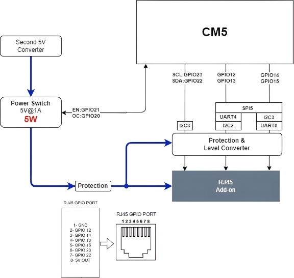
GPIO Add-on port (RJ45)
The GPIO port exposes six configurable CM5 pins over an RJ45 connector, providing I²C, UART, and SPI to ALPON Edge Add-on modules. Signals are 3.3 V logic with built-in level conversion, ESD protection, and 1 kΩ hardware pull-ups.
Pin assignment
| RJ45 Pin | CM5 GPIO | Alternate Functions |
|---|---|---|
| 1 | GND | Ground |
| 2 | GPIO 12 | SPI5_CSn[0], UART4_TX, I2C2_SDA |
| 3 | GPIO 14 | SPI5_SIO[0], UART0_TX, I2C3_SDA |
| 4 | GPIO 13 | SPI5_SIO[1], UART4_RX, I2C2_SCL |
| 5 | GPIO 15 | SPI5_SCLK, UART0_RX, I2C3_SCL |
| 6 | GPIO 23 | I2C3_SCL |
| 7 | GPIO 22 | I2C3_SDA |
| 8 | 5V OUT | 5 V power output, max. 1 A — gated by power switch (GPIO 21) |
Electrical characteristics
| Signal Voltage | 3.3 V logic (with level converter and ESD protection) |
| Pull-up Resistors | 1 kΩ hardware pull-up on every signal pin |
| Power Output | 5 V @ 1 A maximum (5 W) |
| Power Switch Enable | GPIO 21 — must be set HIGH before I/O |
| Fault Detection | GPIO 20 — HIGH normally, LOW on overcurrent / overtemperature / reverse voltage |
Power-switch control
The port's 5 V supply and all signal I/O are gated by an on-board power switch. The switch must be explicitly enabled in software before the port becomes active — signals will not propagate while GPIO 21 is LOW.
| Signal | CM5 GPIO | Description |
|---|---|---|
ADDON_PWS_EN | GPIO 21 | Power switch enable. Drive HIGH to activate the port. I/O does not work until this pin is HIGH. |
ADDON_PWS_FAULT | GPIO 20 | Fault indicator. Reads HIGH during normal operation. Goes LOW on overcurrent, overtemperature, or reverse-voltage events — the hardware also cuts the 5 V rail automatically. |
Minimum enable sequence:
# Enable GPIO Add-on port power rail
pinctrl set 21 op dh      # drive GPIO 21 HIGH
pinctrl get 20            # read fault line — should return 1 (HIGH)
LED indicators
Four LEDs on the front face report system state. All LEDs are driven via the TCA6408 I²C I/O expander at address 0x20 on the I²C1 bus (SDA: GPIO 2, SCL: GPIO 3).
| # | LED | Expander Pin | Logic | Description |
|---|---|---|---|---|
| User RGB | P2 (R) · P3 (G) · P4 (B) | Active LOW | Freely programmable. Reserved for user applications. | |
| Status RGB | P5 (R) · P6 (G) · P7 (B) | Active LOW | Controlled by the ALPON OS and Sixfab Connect agent. | |
| Status (green) | P0 | Active LOW | Connection / application status indicator. | |
| Power | P1 | Active HIGH | Lights when any valid power input is present. |
0 to the expander pin to turn the color on.
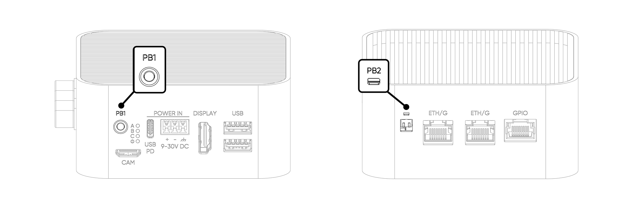
Push buttons
Two user-programmable push buttons — PB1 on the front face and PB2 on the rear face. Both lines are pulled HIGH by default and read LOW while pressed.
| Button | CM5 GPIO | Default Behavior |
|---|---|---|
| PB1 (front) | GPIO 5 | Pulled HIGH · LOW when pressed · user-defined action |
| PB2 (rear) | GPIO 6 | Pulled HIGH · LOW when pressed · user-defined action |
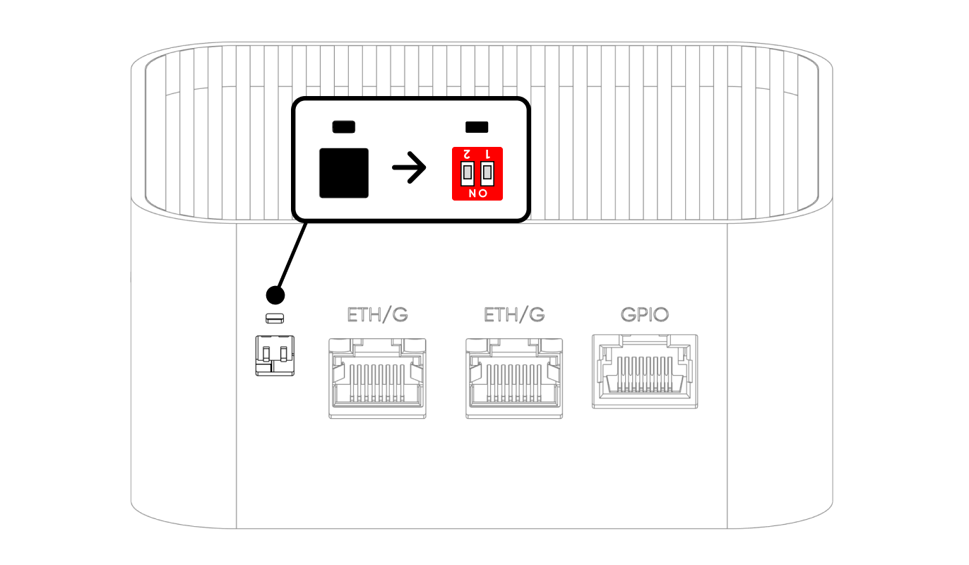
Watchdog & Boot/Burn switches
Two DIP switches are accessible under a silicone cap on the rear face. Both ship OFF by default and should remain OFF during normal operation. Use a pointed tool to gently lift the cap from its notch.
| Position | SW1 — Watchdog | SW2 — Boot/Burn |
|---|---|---|
| ON | Watchdog Disabled | Burn (Image Flash Mode) |
| OFF (Default) | Watchdog Enabled | Boot (Operating Mode) |
SW1 — Hardware watchdog
The hardware watchdog monitors system liveness independently of the OS. When enabled (SW1 OFF), the CM5 must toggle GPIO 16 at least once every 5 minutes. If no trigger arrives, the watchdog cuts all power to the device, waits 3 seconds, then re-applies power to force a cold reboot.
- Trigger pin:
GPIO 16 - Timeout: 5 minutes
- Recommended period: a 2-second HIGH pulse every 60 seconds
- Status read pin:
GPIO 8— HIGH when SW1 = OFF (watchdog enabled), LOW when SW1 = ON (watchdog disabled) - Disable method: physical SW1 only — no software command exists
SW2 — Boot / Burn mode
SW2 selects between normal operation (Boot) and CM5 image flashing over USB-C (Burn). In Burn mode, the USB-C port exposes the CM5's flashing interface to a host PC running rpiboot.
Antenna connectors
Four SMA connectors on the rear face carry the wireless interfaces. Labels on the enclosure identify each port.
| Antenna | Label | SMA Connector | Notes |
|---|---|---|---|
| LTE Main | L | Female | Primary cellular RF path |
| LTE Diversity | L | Female | Rx diversity for improved link budget |
| GNSS / GPS | G | Female | Active antenna; must face the sky |
| Wi-Fi / BLE | W | Male (RP-SMA) | 2.4 GHz + 5 GHz |
For radiation patterns, gain charts, and supported LTE bands, see Connectivity & Antenna Specifications.
Internal bus topology
Understanding how I/O maps back to the CM5 helps diagnose throughput and power-sharing issues. The diagram below summarizes the primary data paths.
| Interface | CM5 Connection | Notes |
|---|---|---|
| USB 3.0 Port 1 | Native USB 3.0 | Direct connection to CM5 |
| USB 3.0 Port 2 + ETHERNET 1 | Native USB 3.0 → TUSB8020 hub | Shared 5 Gbps upstream. ETHERNET 1 reaches Gigabit via RTL8153B USB ↔ GbE bridge. |
| ETHERNET 0 | Native Ethernet MAC | Carries PoE+ on PoE variants |
| NVMe SSD + DEEPX NPU | PCIe Gen3 → ASM2806I packet switch | PCIe lane is fanned out to both the SSD and the M.2 AI accelerator |
| Camera Port | MIPI CSI-2 (MIPI 1 on CM5) | 2-lane, camera only |
| HDMI Display | CM5 HDMI 0 | 4Kp60 HEVC |
| LEDs | I²C1 → TCA6408 @ 0x20 | Expander-driven |
| GPIO Add-on Port | CM5 GPIO 12–15, 22, 23 | Gated by GPIO 21 power switch |
Where to next
Updated about 2 hours ago