Package Includes
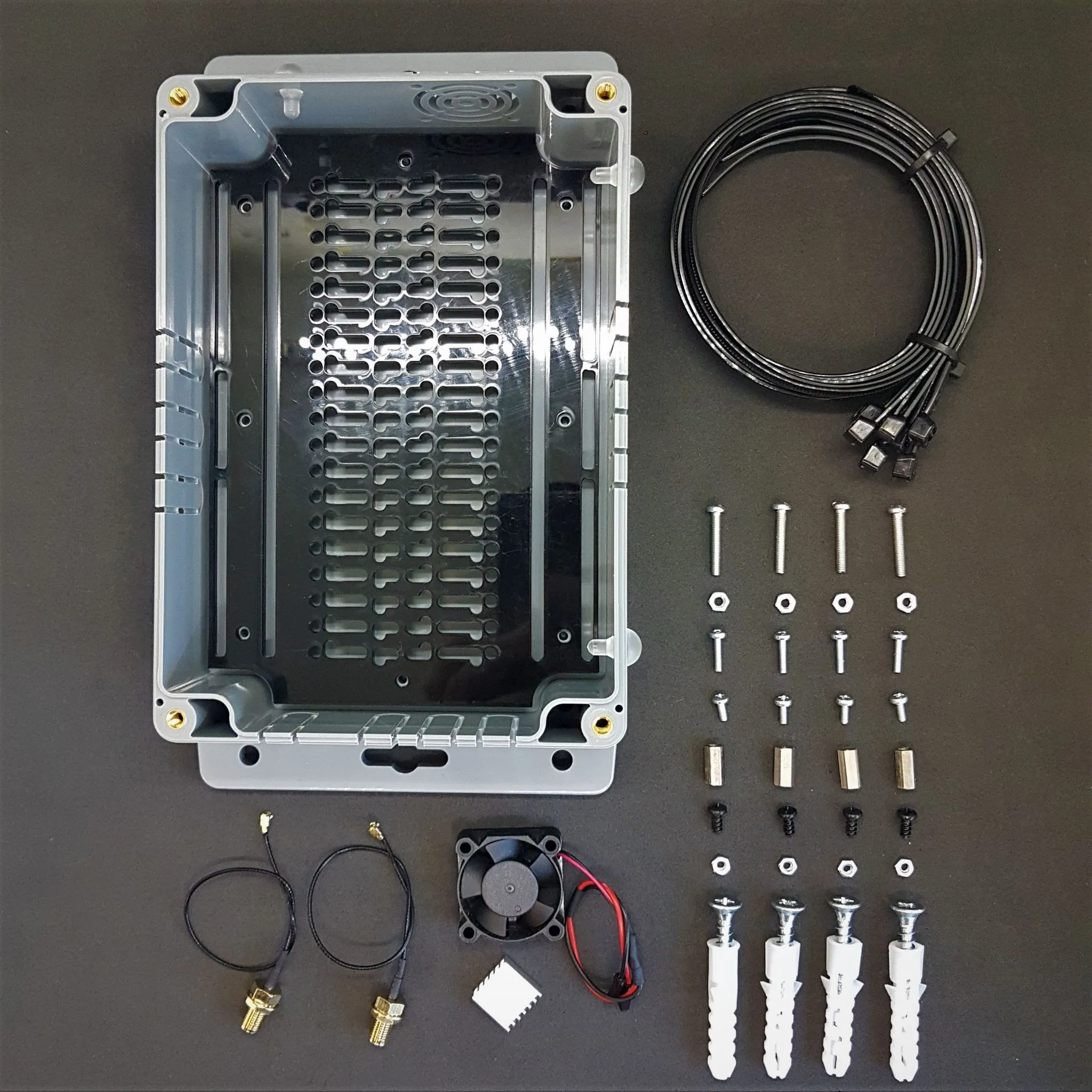
- 1 x Indoor case with clear acrylic top cover
- 1 x Acrylic PCB base plate for the mounting interface between boards and case bottom
- 1 x 5V Cooling Fan
- 2 x SMA to u.FL RF Adapter Cable
- 1 x Raspberry Pi Aluminium Heatsink Set 4 Pieces
- 3 x Plastic plugs for unused antenna slots on side panels
- 4 x M5x30mm Stainless Steel Screw with plastic wall fixing plugs
- 6 x M3x9mm Stainless Steel Screw for fixing the base plate to the case bottom
- 4 x M2.5x12mm Stainless Steel Screw for fixing Raspberry Pi to the base plate
- 4 x M2.5x8mm Stainless Steel Screw for board stacking
- 2 x M2.5x11mm Brass Standoff for board stacking
- 8 x M2.5 Stainless Steel Flat Washer
- 8 x M2.5 Stainless Steel Nut
- 4 x M3 Stainless Steel Screw for Fan
- 2 x M3 Stainless Steel Nut
- 8 x 400mm Heavy-duty zip-tie
Assembly Directions
The indoor enclosure is designed with many cable entry points and Rpi mounting plexiglass to provide flexibility for many projects. The assembly instructions here are prepared for a single application and to give you an idea of the usage patterns. You can apply in all kinds of different combinations according to your project and application. If you have any questions, please contact us!
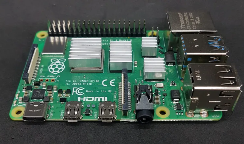
First, Assemble the Raspberry Pi coolers to the Raspberry Pi.
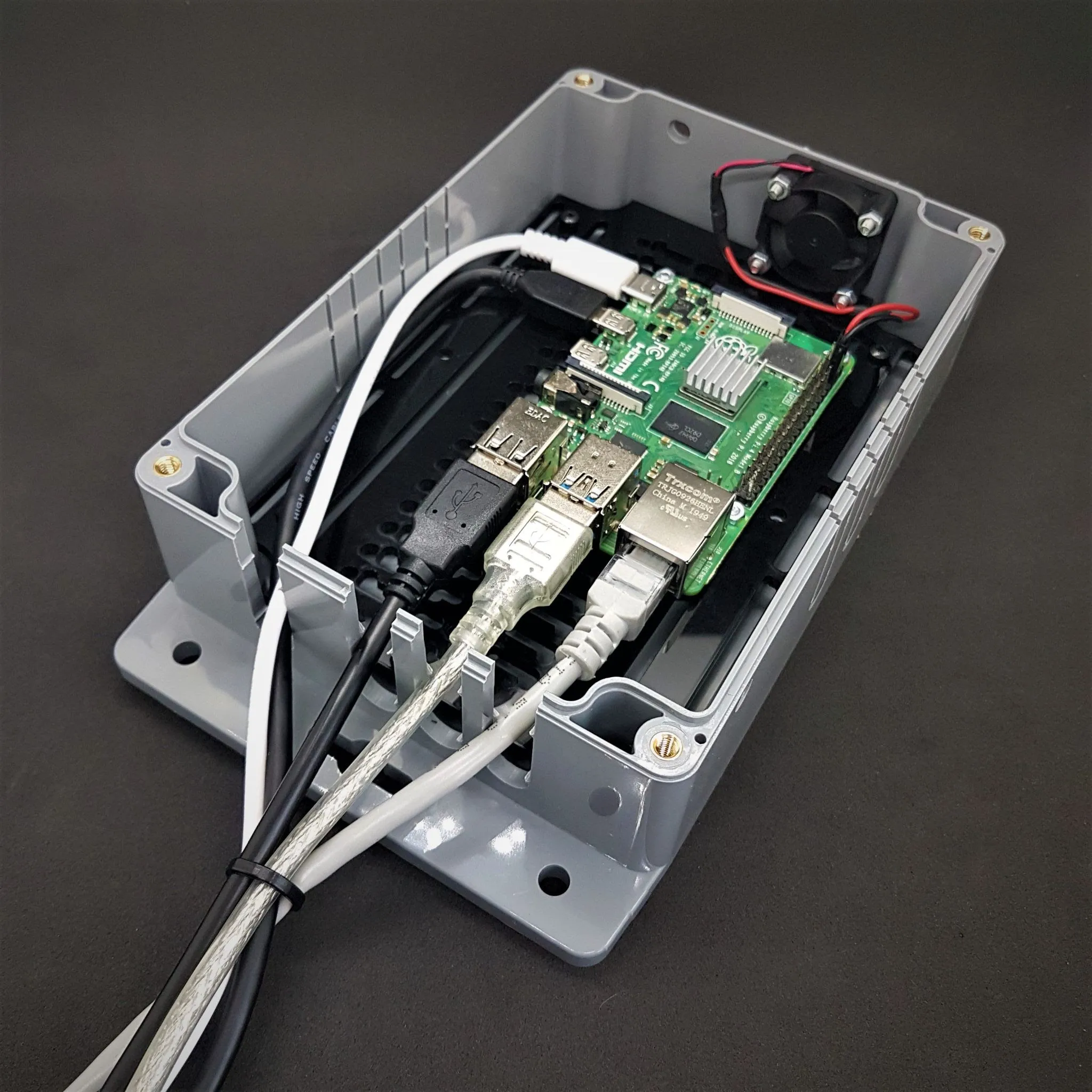
Plug the cables and SD card you use in your project into the RPi.
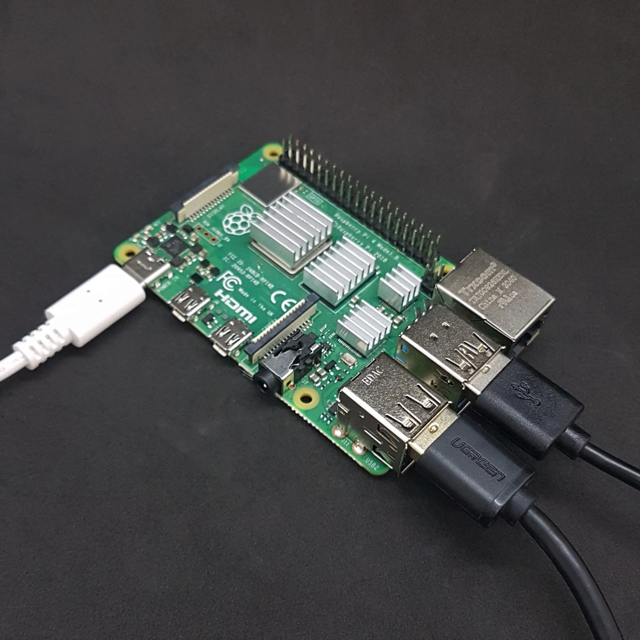
It is important where you will mount the box to determine the cable entry points. Will the cables come out of the box on the long side or the short side? Are you going to use an antenna? Determine which cable entry points to open by paying attention to these issues and putting the RPi in the box.
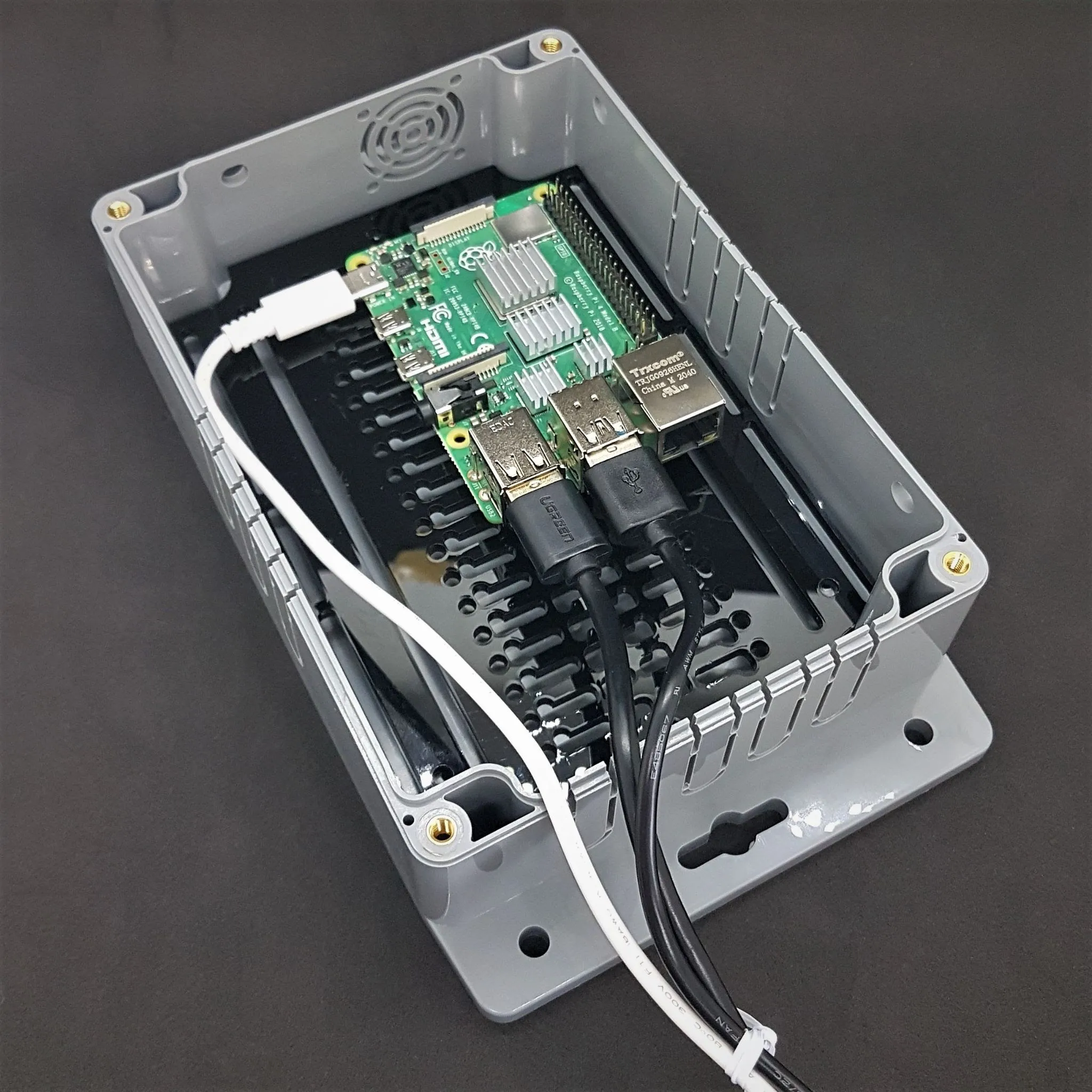
Break the cable entry points you have determined with pliers or similar tools. You can also cut it with a utility knife. It is useful to review the whole plan a few times before breaking it. Unfortunately, it is not possible to put the broken points back on.
Caution: Do not try to break it with your hands!
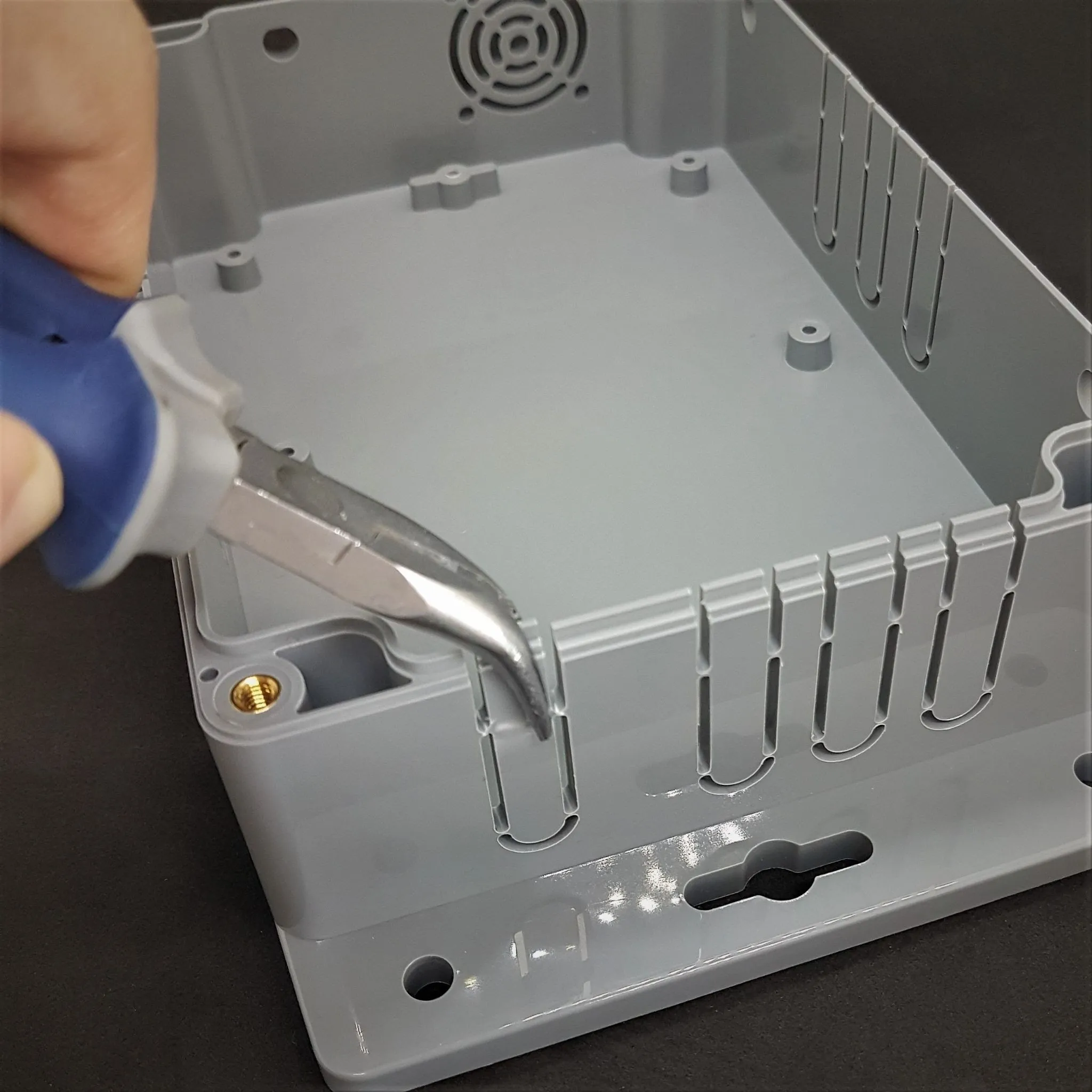
Now, to mount the RPi, we first need to determine where to mount it. For this, we pass the cables through the transition points and place them in a suitable place inside.
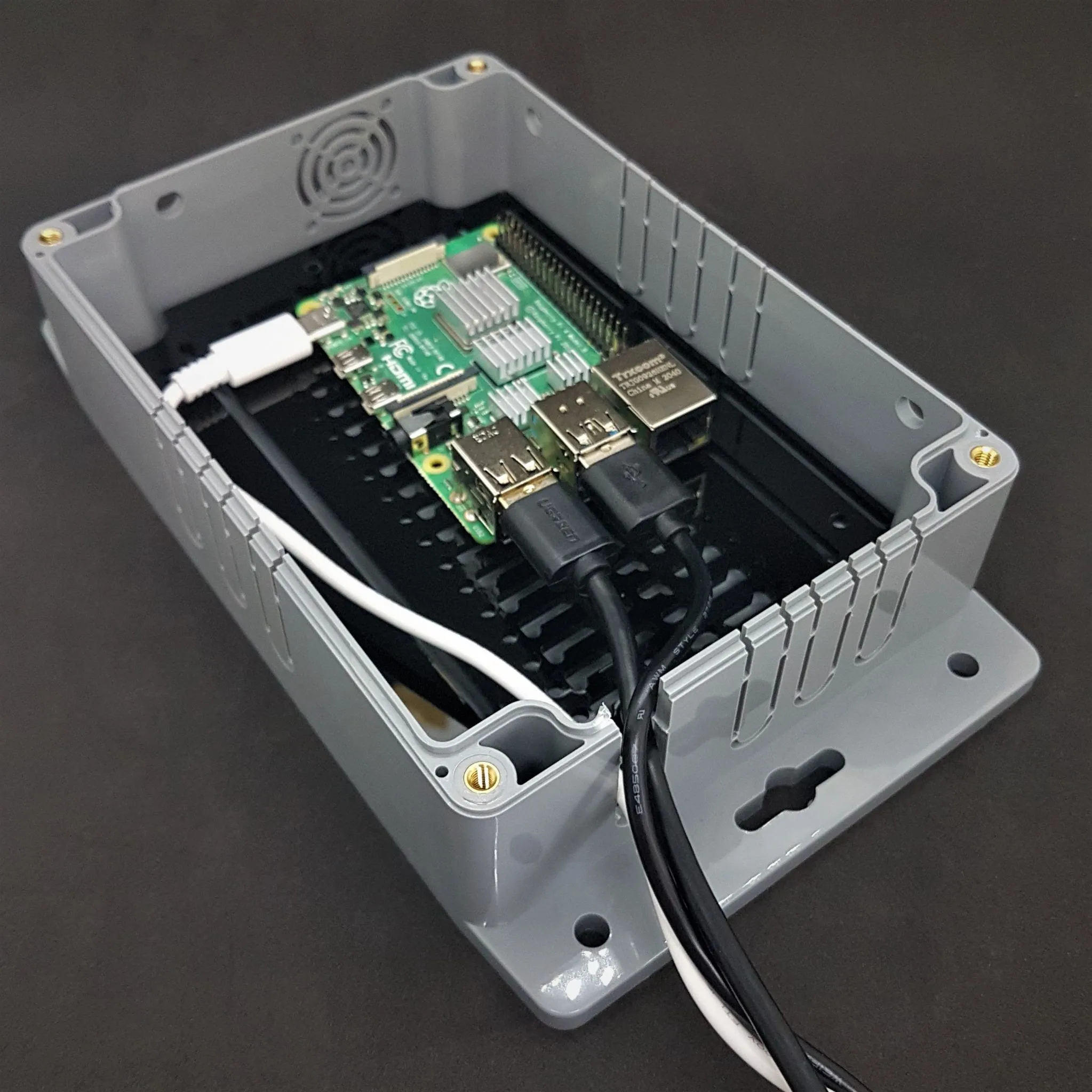
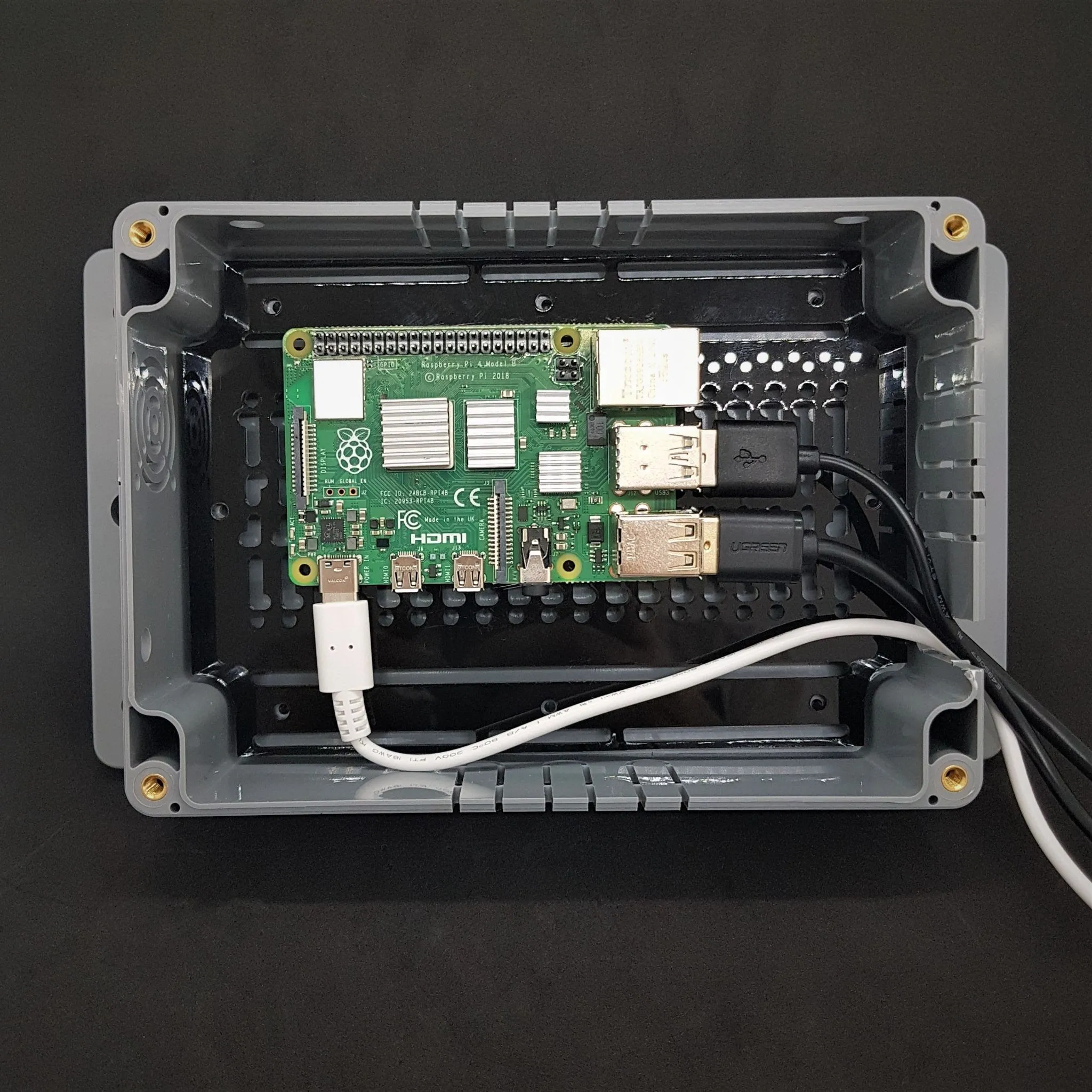
Assemble the RPi to the designated place in the order of 12mm.
Screw mounting sequence: Screw --> Flat Washer --> Plexi --> Nut --> Raspberry Pi
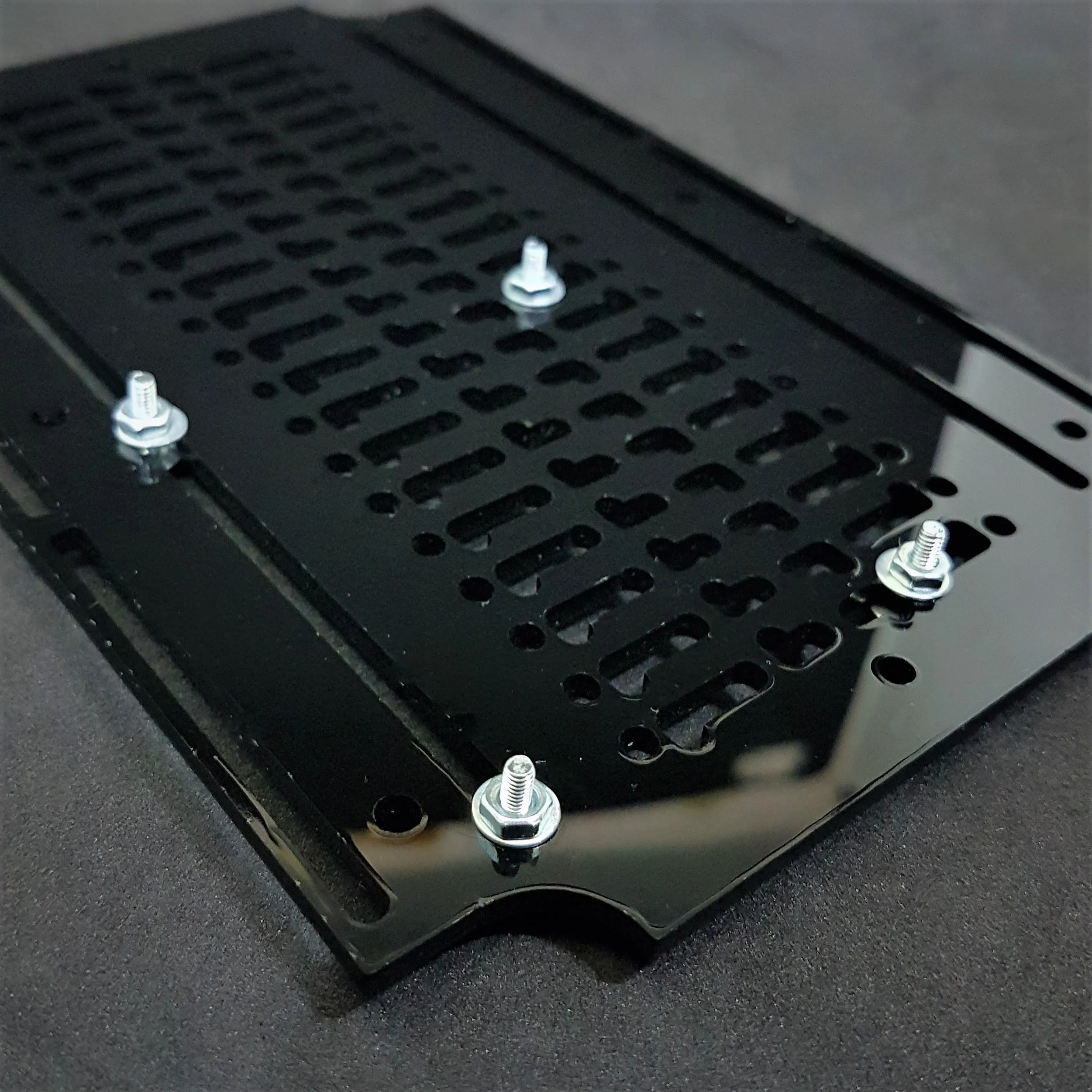
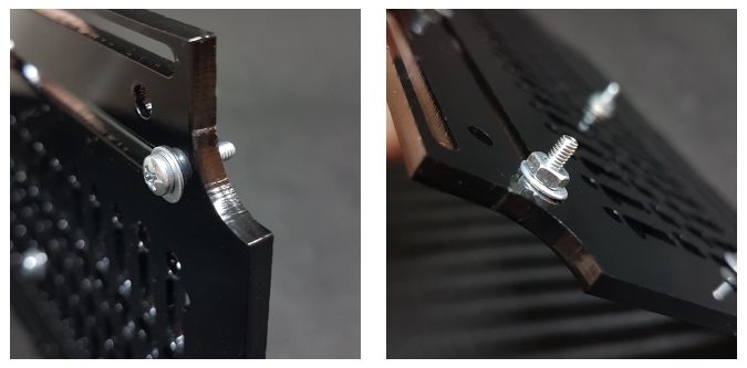
Plug the RPi into place by plugging in the RPi cables. If you are using a HAT, fix the RPi completely with the Standoffs. If not, using with nuts.
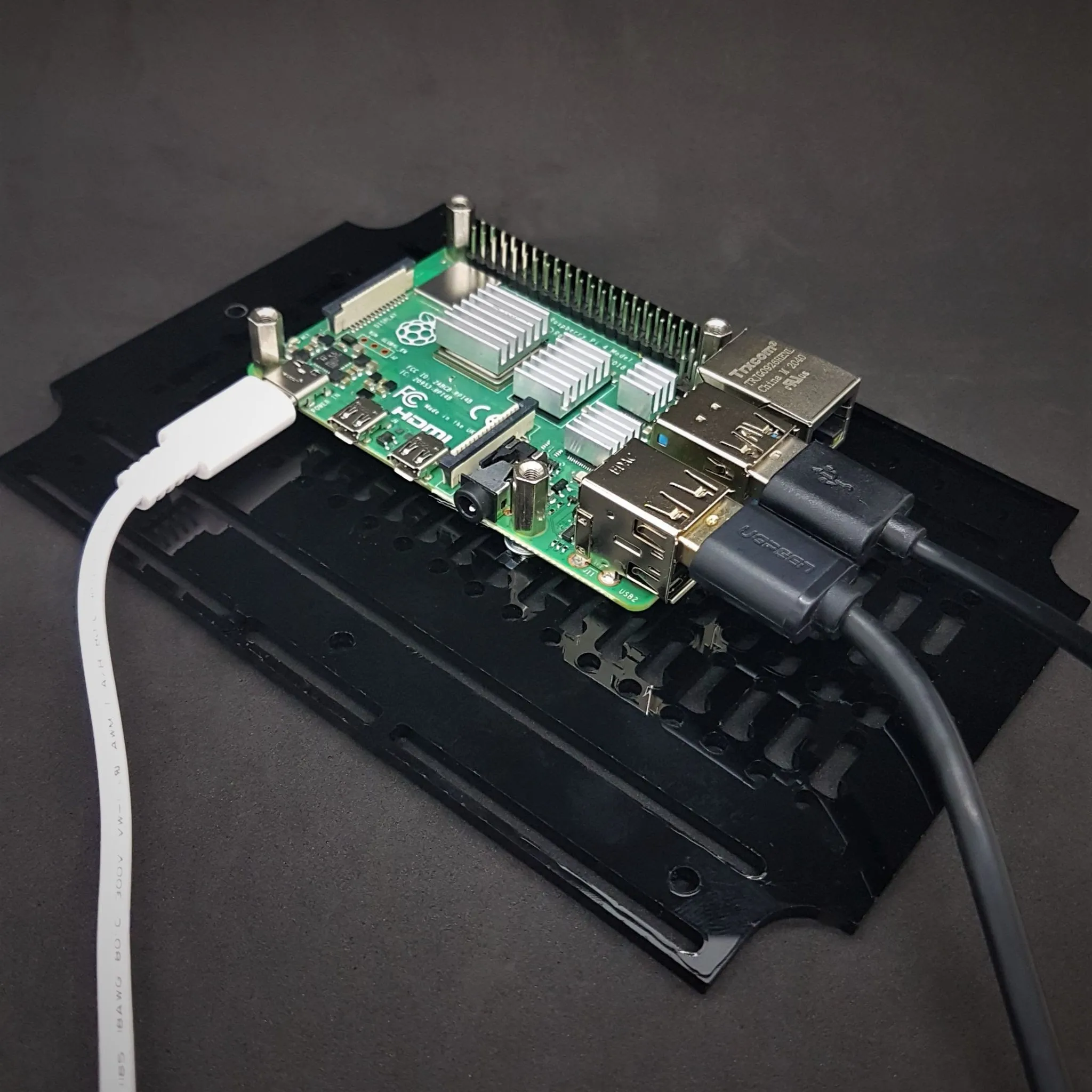
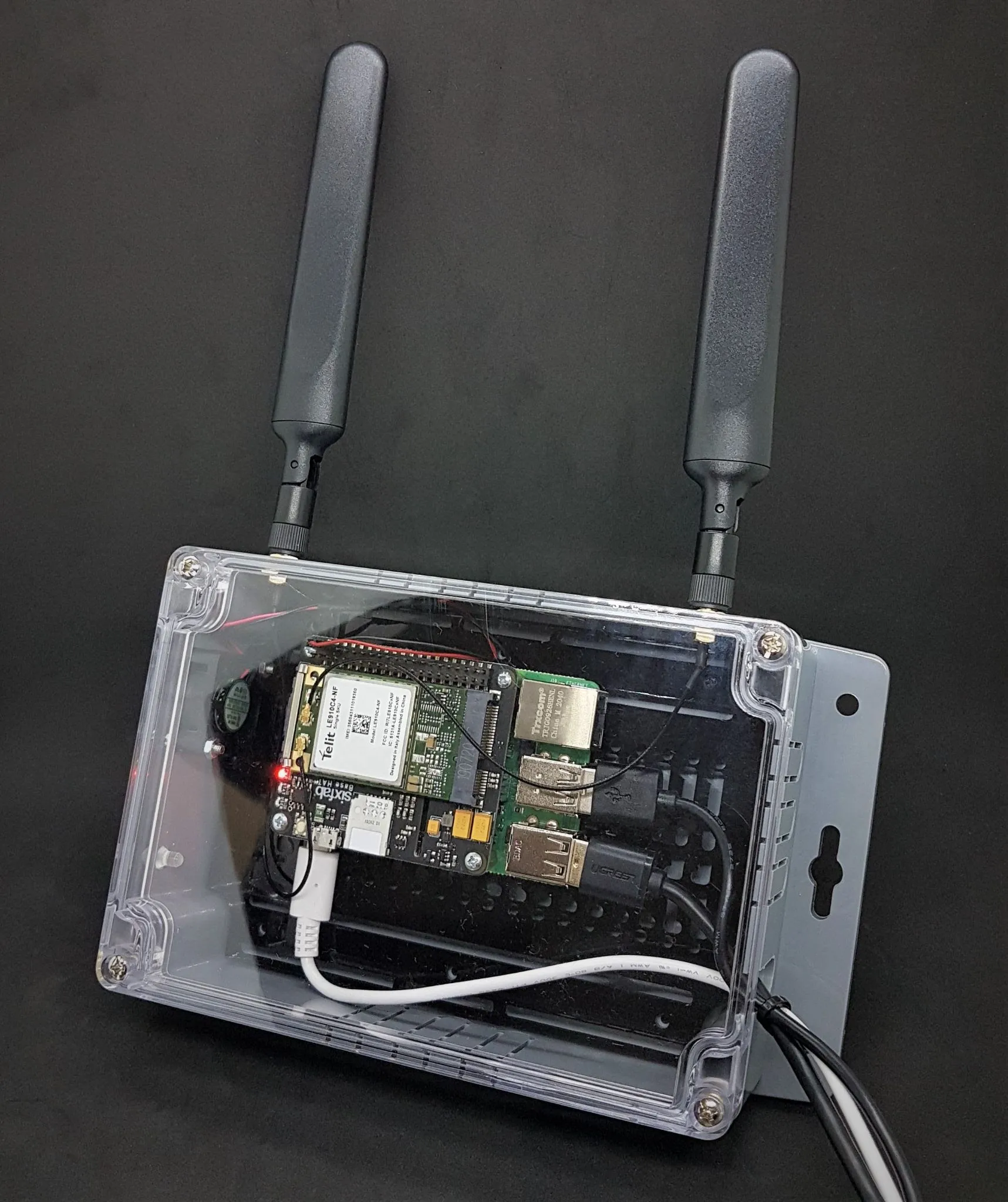
Mount the HAT to the RPi with 8 mm screws. Since the fan will be connected, you should use a long pin header. And insert the SIM card.
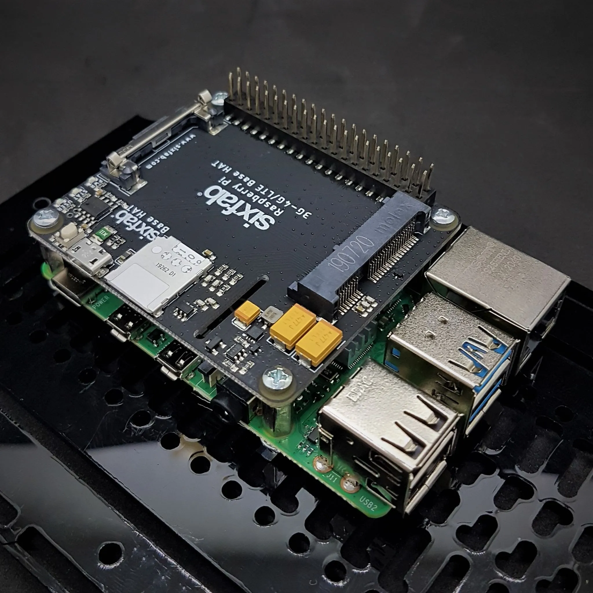
Note: Using external antennas is optional.
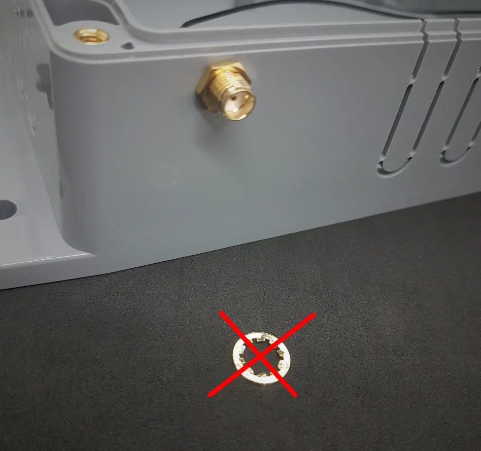
Install SMA-u.FL cable adapters in the box. Do not install washers of SMA sockets when installing them.
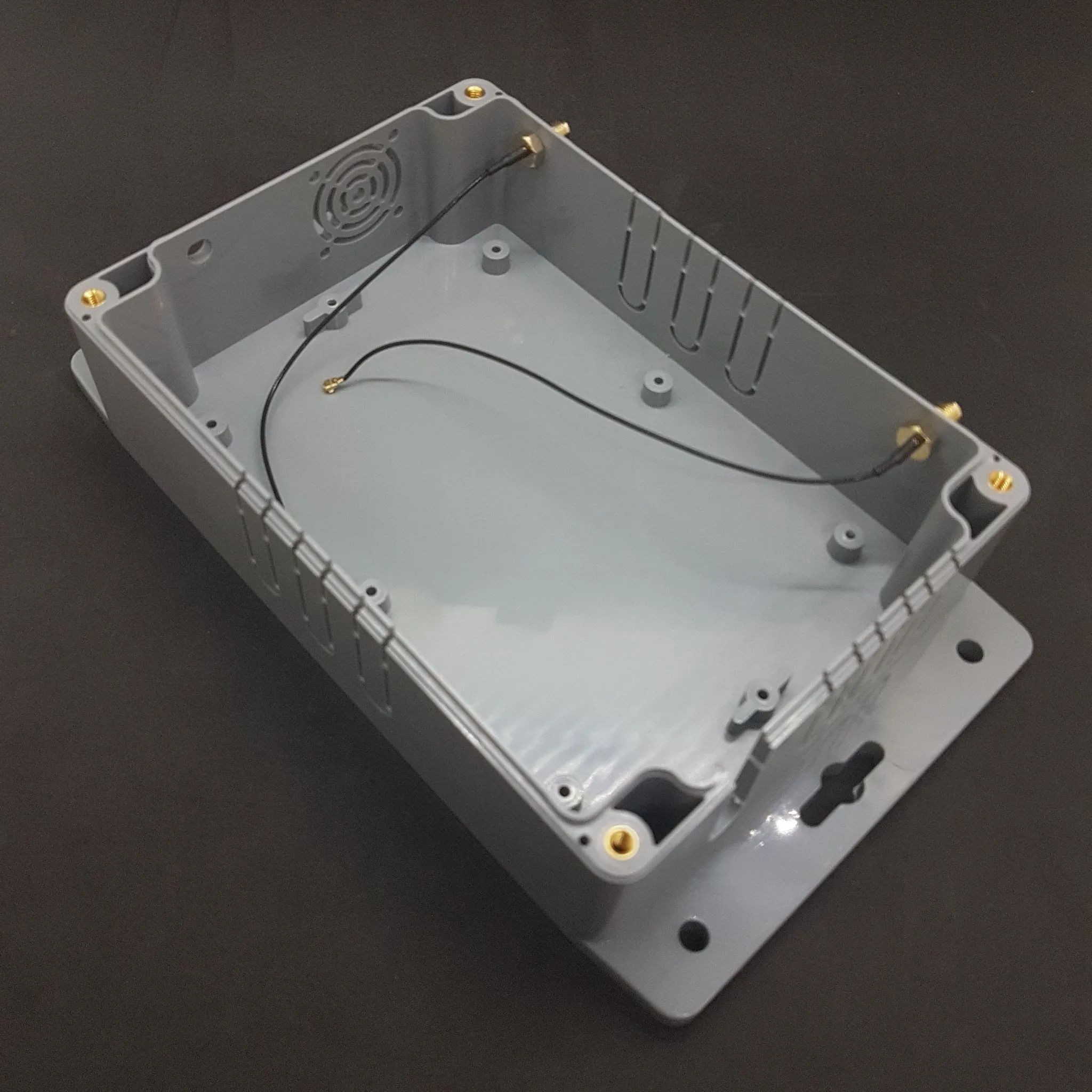
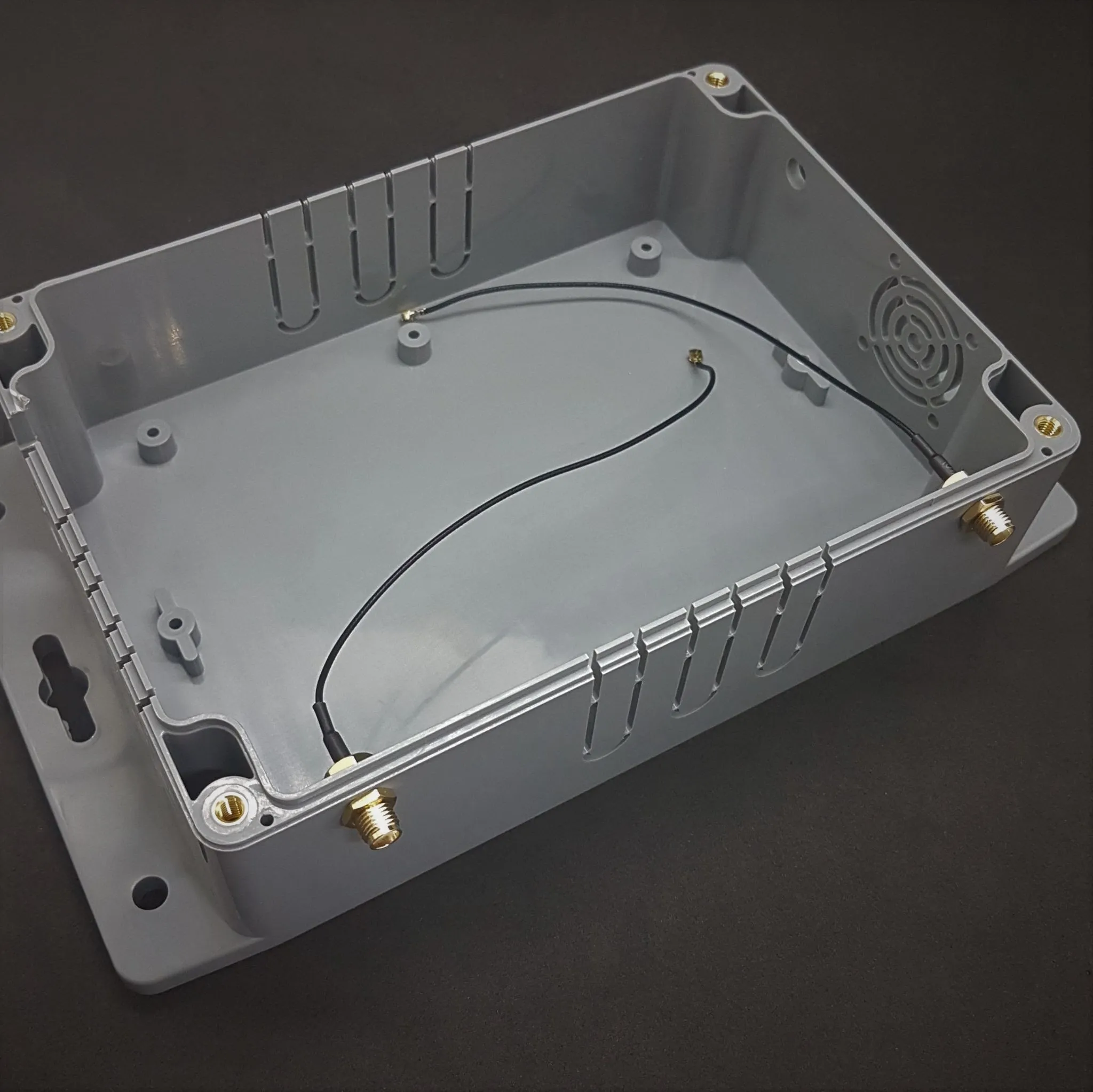
Plug the cables into the RPI. Install LTE module on the HAT. Place it in the box and plug the u.FL cables into the module.
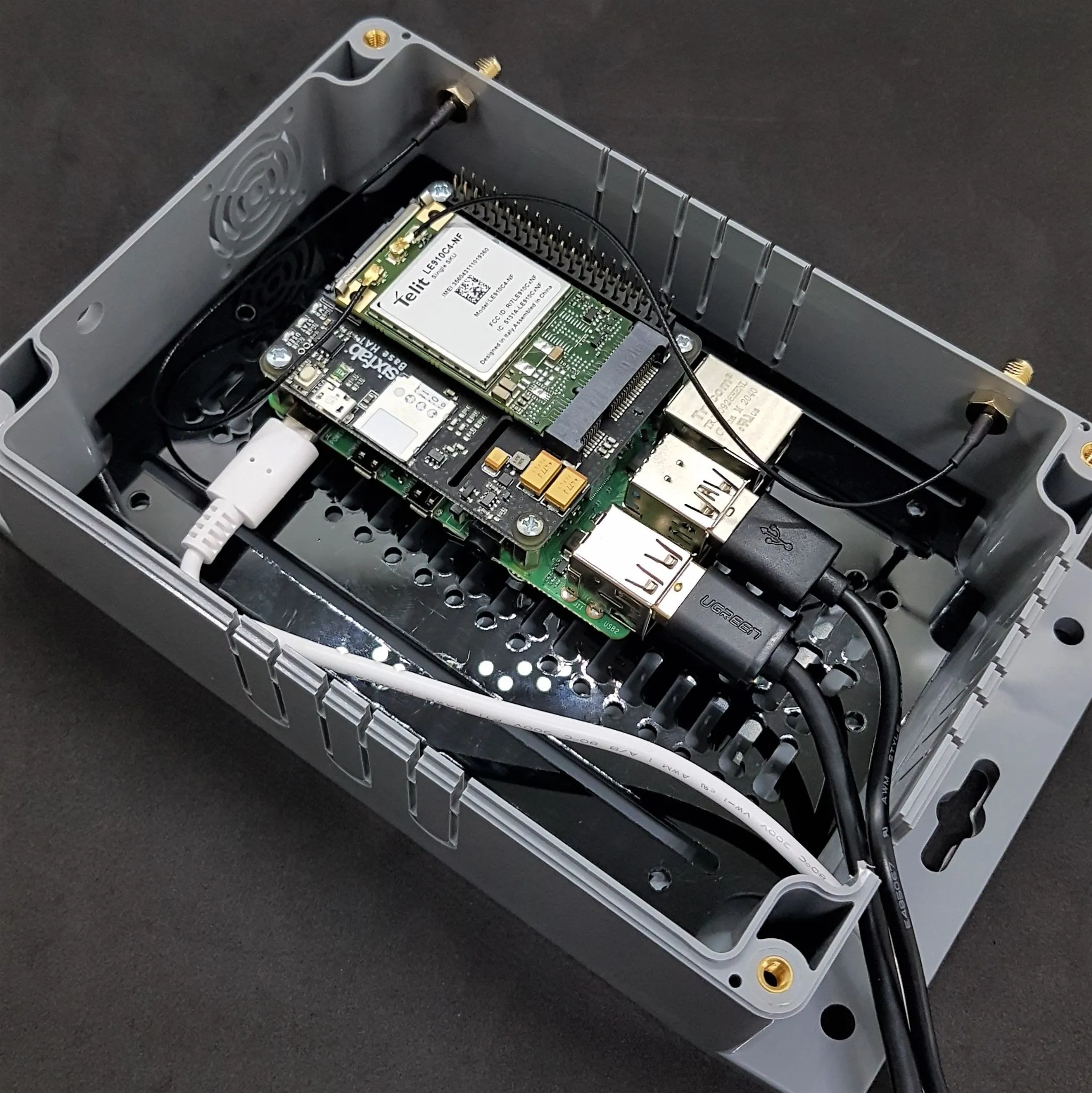
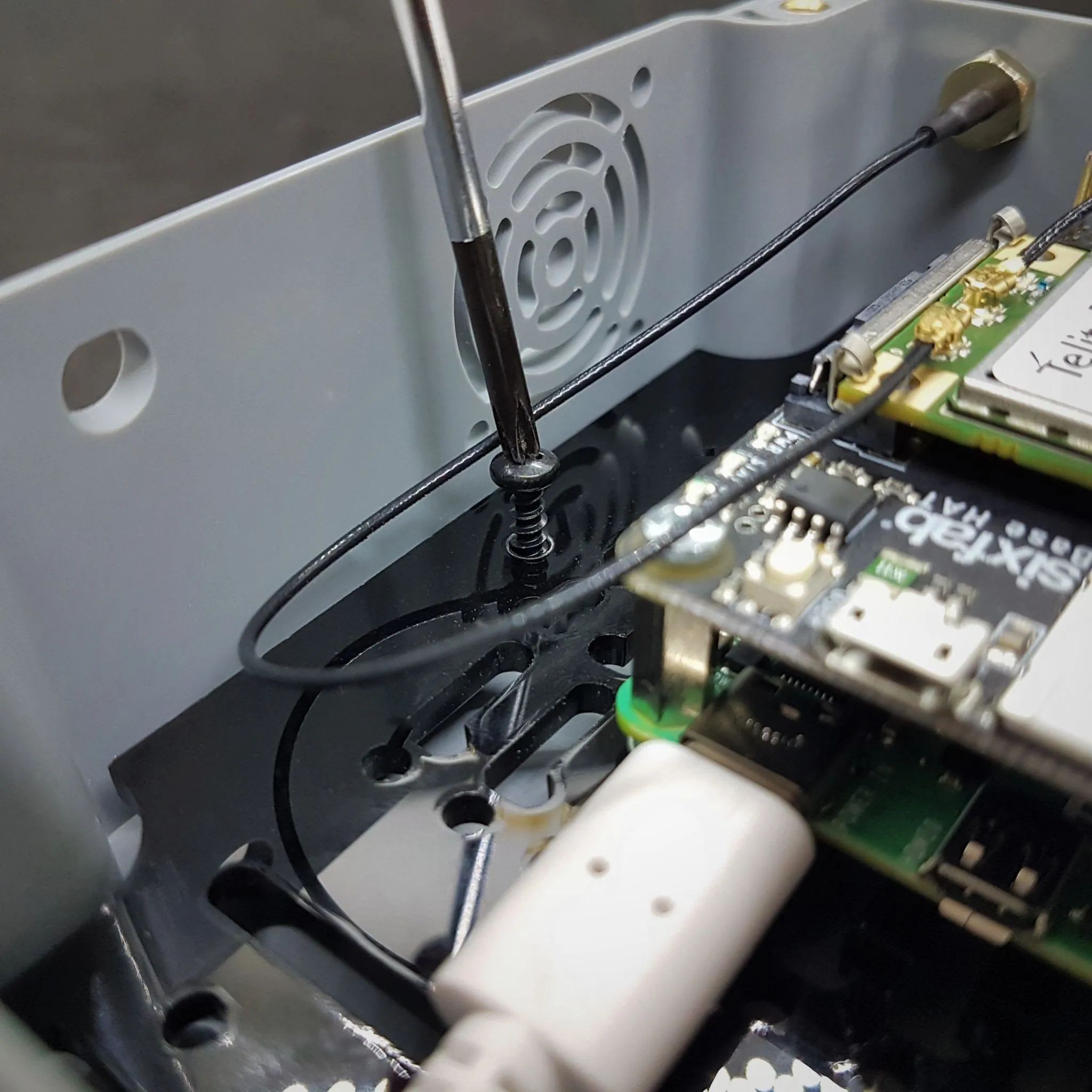
Fix the acrylic base plate with black screws.
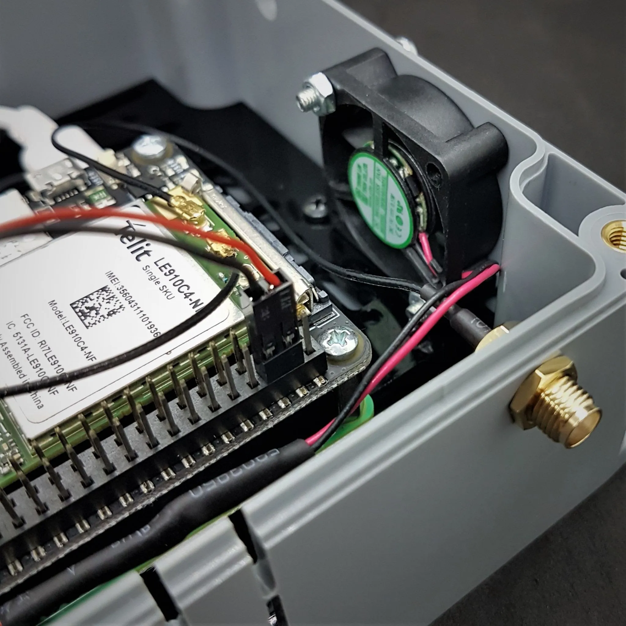
Fix the fan with the label facing inwards. 2 screws are sufficient, but you can also use 4 screws. You can mount fan cables to the RPi as seen on pictures, pins 4 and 6, paying attention to the +/- directions.
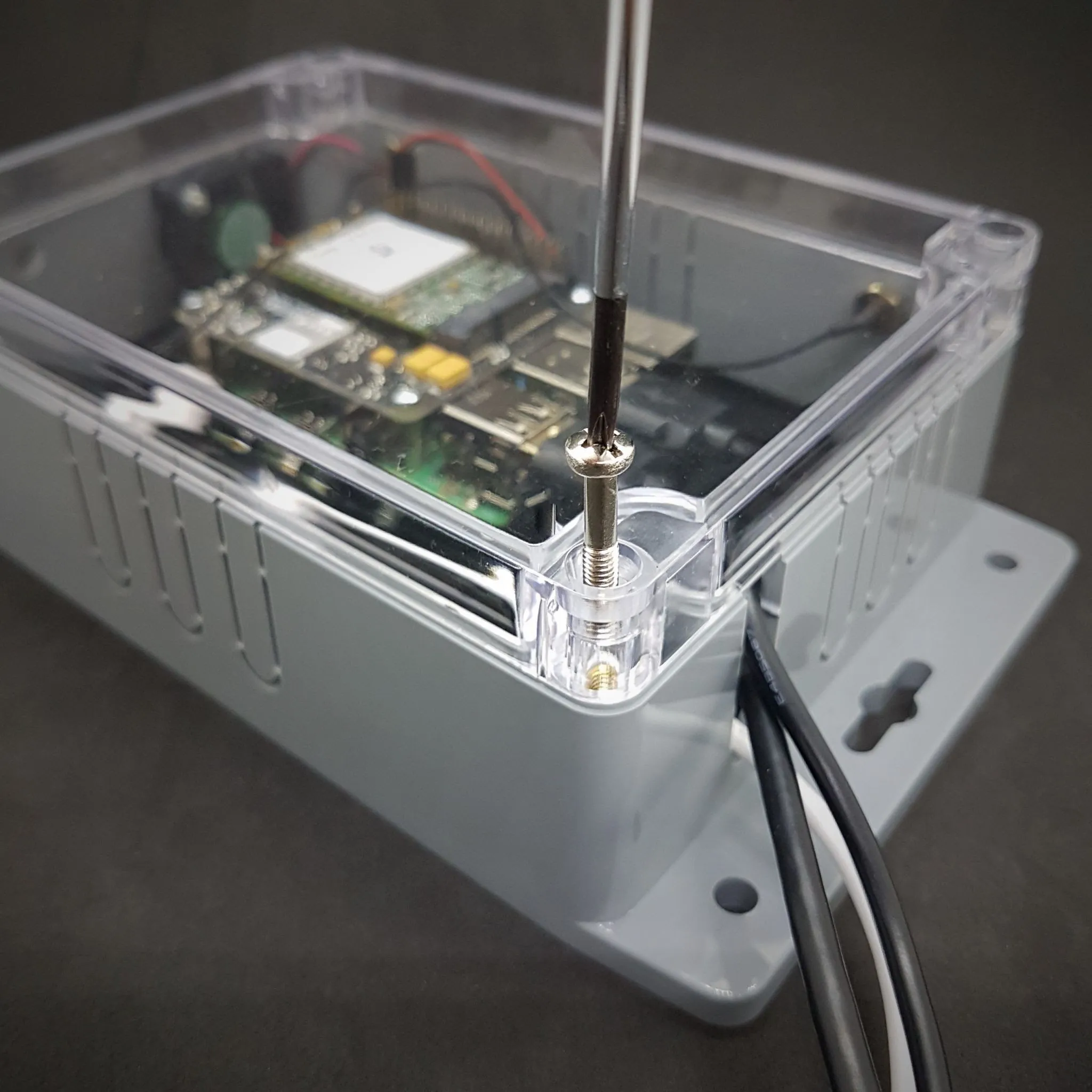
And put on the cover, tighten the screws.
With the white pieces coming out of the set, you can close the idle antenna holes if you want.
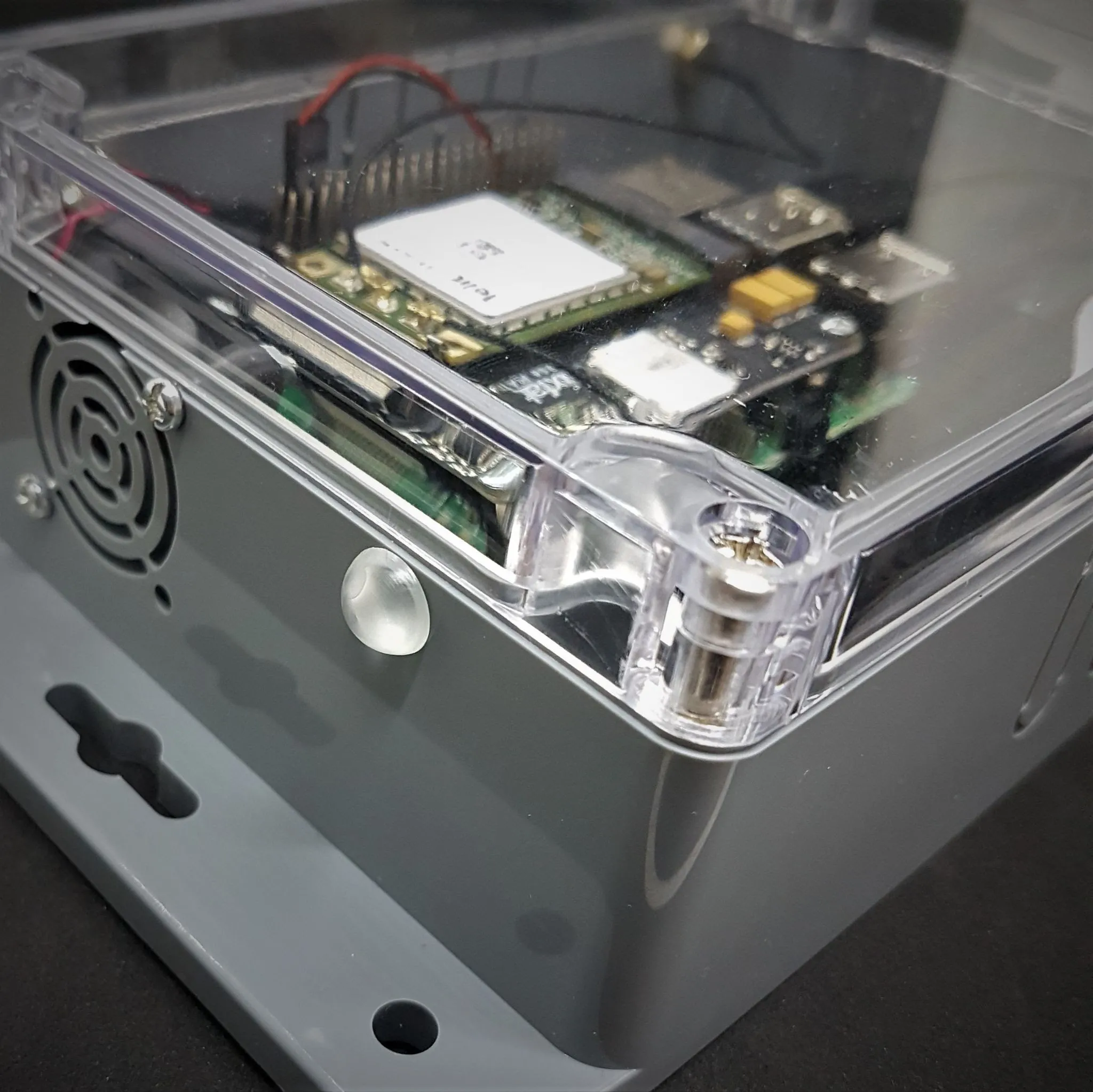
Your setup is ready! Power up and test it. 🚀
